PN#
500-12300
Page
2
Rev. C, 6/09
BLU
E
RED
3. WIRING
3.1 POWER, DATA AND KEYPAD WIRING
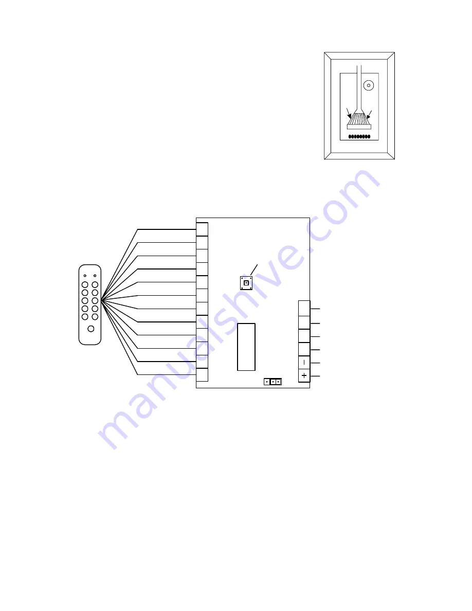
Note that the cable connector plugs into the rear of the circuit board
which is on the opposite side of the keypad. It is possible to plug the
cable connector incorrectly, so follow the drawing to the right for correct
orientation. Also, be careful not to pull on the cable as you route it
towards the CPU board or you could pull the connector out.
Figure 1 shows the DK-16W CPU Board. You will make connections to
the 18 terminals as shown in the drawing and either leave the jumper
block in the factory set position (connects pins 2 and 3) if you plan to
power the DK-16W with 12 VDC or move the jumper to connect pins 1
and 2 if you will be using 5 VDC. Note that operation at 12 volts with
the jumper block in the 5 volt position can damage the unit.
Note that the DK-16W will not operate on AC power. It will, however, accept full wave
rectified DC power (trans bridge rectifier) when it is being powered by 12 VDC.
When it is being powered by 5 VDC, the voltage must be regulated (+/- 1/2 volt). Be sure
to observe polarity when you power the DK-16W.
FIG. 1: OVERVIEW OF CPU BOARD
GRN
YEL
RED
BLU
WH
T
BLK
GRY
BRN
BGE
ORG
P
NK
VIO
D0
D1
LED
X
MIT
GREEN
YELLOW
RED
BLUE
WHITE
BLACK
GRAY
BROWN
BEIGE
ORANGE
PINK
VIOLET
MICRO-
PROCESSOR
FACILITY CODE
PROGRAM
BUTTON
TRANSMIT DATA
LED (FROM SYSTEM)
DATA 1
0 VDC (NEG)
+5 OR +12 VDC
DATA 0
1
3
2
JUMPER TO SET
VOLTAGE
FACTORY SET 2/3 = 12 V
CHANGE TO 1/2 FOR 5 V
There are 12 color coded wires in the keypad cable. Refer to Figure 1 and connect each wire to
the indicated terminal on the CPU Board. No other connections may be made to these terminals
(except if two keypads are used with one CPU board).
The DK-16W will draw a maximum of 30 mA at 5 VDC or 12 VDC.
The Weigand output terminals: Data 0 and Data 1 connect to the appropriate inputs of the
access control system. The wire run maximum distance for reliable operation depends on the
wire gauge. A guide line is 200 ft. for 22 gauge; 300 ft. for 20 gauge and 500 ft. for 18 gauge.
3.2 LED AND “TRANSMIT DATA” WIRING
The LED’s on the DK-16W follow the convention for card readers. When a “high” signal (+5
VDC) is connected to the LED terminal, the red LED will be on and the green LED will be off.


