115
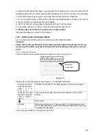
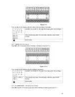
Figure 3-13
You can refer to the following sheet for alarm input and output information.
1
,
2
,
3
,
4
,
5
,
6
,
7
,
8
,
9
,
10
,
11
,
12
,
13
,
14
,
15
,
16
ALARM 1 to ALARM 16. The alarm becomes active in low voltage.
NO1 C1
,
NO2 C2
,
NO3 C3
,
NO4 C4,
NO5 C5 NC5
The first four are four groups of normal open activation output
(on/off button)
NO5 C5 NC5 is a group of NO/NC activation output (on/off button)
CTRL 12V
Control power output. The power output is off when the alarm is
canceled.
+12V
It is rated power output.
Earth cable.
485 A/B
485 communication port. They are used to control devices such as
PTZ. Please parallel connect 120T
Ω
between A/B cables if there are
too many PTZ decoders.
3.8.1.13
HD-SDI 1080P 2U Series
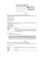
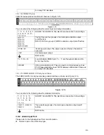
HD-SDI 1080P 2U series interface is shown as below. See Figure 3-14.
Figure 3-14
You can refer to the following sheet for alarm input and output information.
1
,
2
,
3
,
4
,
5
,
6
,
7
,
8
,
9
,
10
,
11
,
12
,
13
,
14
,
15
,
16
ALARM 1 to ALARM 16. The alarm becomes active in low voltage.
NO1 C1
,
NO2 C2
,
NO3 C3
,
NO4 C4,
NO5 C5 NC5
The first four are four groups of normal open activation output
(on/off button)
NO5 C5 NC5 is a group of NO/NC activation output (on/off button)
CTRL 12V
Control power output. The power output is off when the alarm is
canceled.
+12V
It is rated power output.
Earth cable.
485 A/B
485 communication port. They are used to control devices such as
PTZ. Please parallel connect 120T
Ω
between A/B cables if there are
too many PTZ decoders.
T+, T-, R+, R-
4-pin full-duplex RS485 port. T+
,
T- are the output cable and R+
,
R- are input cable.
485 A/B
485 communication port. They are used to control devices such as
PTZ. Please parallel connect 120T
Ω
between A/B cables if there are
Summary of Contents for DVR-HD016240M
Page 97: ...86 Figure 2 30 2 3 4 HD SDI 1080P 1U Series The connection sample is shown as in Figure 2 31...
Page 99: ...88 Figure 2 32 2 3 6 General 1 5U series Please refer to Figure 2 33 for connection sample...
Page 130: ...119 HD SDI 1 5U Mini 2U Series Figure 3 18...
Page 152: ...141 Figure 4 27 Figure 4 28 Figure 4 29...
Page 157: ...146 Figure 4 34 Figure 4 35 Figure 4 36...
Page 165: ...154 Figure 4 52...
Page 169: ...158 Figure 5 3 Figure 5 4 Figure 5 5 Figure 5 6...
Page 177: ...166 Figure 5 16 Figure 5 17 Figure 5 18 5 3 5 3 NTP Setup...
Page 218: ...207 Figure 6 11...
Page 288: ...277 Maxtor DiamondMax 20 STM3250820AS 250G SATA...


