62
2
Overview and Controls
This section provides information about front panel and rear panel. When you install this series
DVR for the first time, please refer to this part first.
2.1
Front Panel
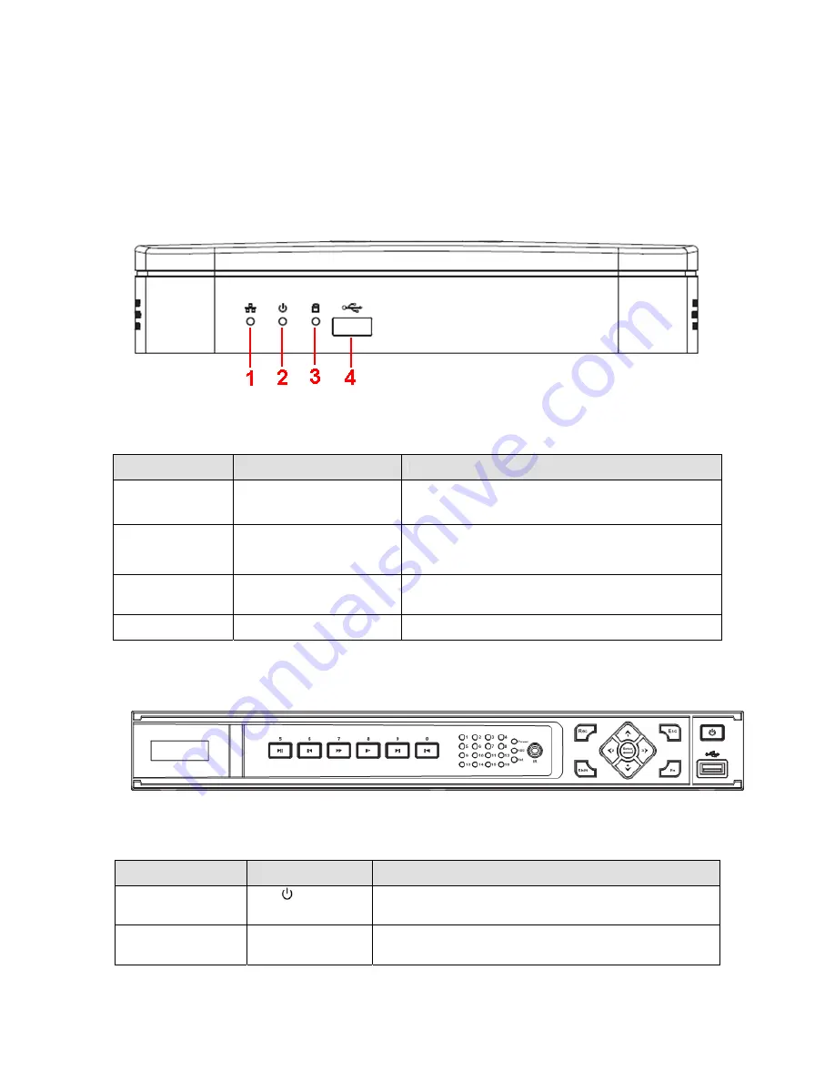
2.1.1 1HDD Full-D1 Smart 1U/1HDD CIF Smart 1U Series
The front panel is shown as below. See Figure 2-1.
Figure 2-1
Please refer to the following sheet for detailed information.
SN
Name
Function
1
Network status indicator
light
The red light becomes on when the network
connection is abnormal.
2
Power indicator light
The red light becomes on when the power
connection is OK.
3
HDD status indictor light
The red light becomes on when HDD is abnormal.
4
USB
USB port
2.1.2 General 1U Series
The front panel is shown as in Figure 2-2.
Figure 2-2
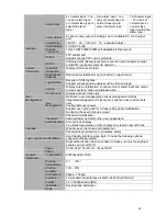
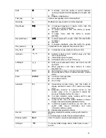
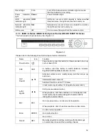
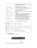
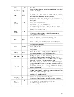
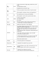
Please refer to the following sheet for front panel button information.
Name
Icon
Function
Power button
Power button, press this button for three seconds to
boot up or shut down DVR.
Number button
Number 0-9 and
etc
z
Input Arabic number
z
Switch channel
Summary of Contents for DVR-HD016240M
Page 97: ...86 Figure 2 30 2 3 4 HD SDI 1080P 1U Series The connection sample is shown as in Figure 2 31...
Page 99: ...88 Figure 2 32 2 3 6 General 1 5U series Please refer to Figure 2 33 for connection sample...
Page 130: ...119 HD SDI 1 5U Mini 2U Series Figure 3 18...
Page 152: ...141 Figure 4 27 Figure 4 28 Figure 4 29...
Page 157: ...146 Figure 4 34 Figure 4 35 Figure 4 36...
Page 165: ...154 Figure 4 52...
Page 169: ...158 Figure 5 3 Figure 5 4 Figure 5 5 Figure 5 6...
Page 177: ...166 Figure 5 16 Figure 5 17 Figure 5 18 5 3 5 3 NTP Setup...
Page 218: ...207 Figure 6 11...
Page 288: ...277 Maxtor DiamondMax 20 STM3250820AS 250G SATA...

