40
C2
C3
3
2
3.1
PREPPING FOR THE REAR MOUNTING
3.1.1 Operator fixed on iron posts
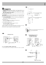
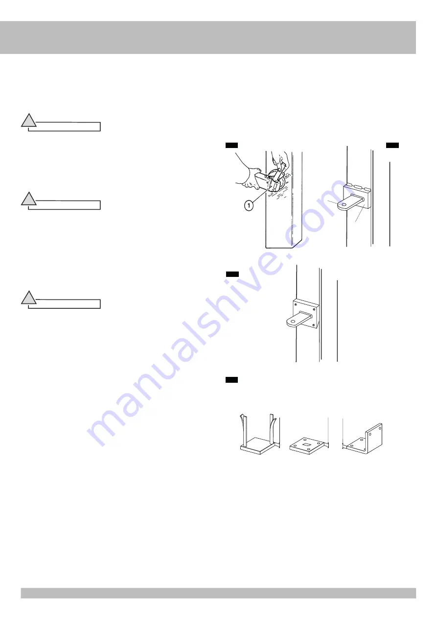
If the gate supporting posts are made of iron, it is necessary to fit a reinforcing plate for welding the rear operator mounting.
Perfectly clean the welding zone for the rear mounting with the special tool (
C2
pos.
1
); make sure to remove any traces of paint or zinc coating.
Position the reinforcing plate (
C3
pos.
2
) in the rear mounting welding zone and weld it on the column, covering it from edge to edge.
The size of the reinforcing plate must be in proportion to the size of the column.
Warning
!
• If the size of the column allows for it, use the RIB standard plate provided.
3.1.2 Operator fixed on wooden posts
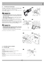
If the gate supporting posts are made of wood, it is necessary to fit a reinforcing plate on the
column, covering it from edge to edge, in the rear mounting welding zone. The plate shall be
fixed firmly on the column by means of fixing screws (
C4
).
The size of the reinforcing plate must be in proportion to the size of the column.
Warning
!
• If the size of the column allows for it, use the RIB standard plate provided.
3.1.3 Operator fixed on masonry posts
If the supporting posts for the gate leaves are made of masonry, fix the special metal plate
complete with anchor bolts used to weld on the rear mounting of the operator to each of them.
Preparing the insets
If mounting insets have to be made in the posts for the rear operator mounting with metal plates,
the measurements shown in fig.
C6
must be adhered to.
Warning
!
Remember that the inset is necessary when the distance between the edge of the post and
the centre of rotation of the gate leaf is greater than the distance
Y
(C1), or when the gate leaf
is anchored to a continuous wall.
Fixing the anchoring plates
Fig. C5 shows some fixing examples by means of different types of plates:
A -
Plate with hooked fitting
B -
Plate with stud bolts, either glued or pressure-fitted
C -
L-plate with stud bolts, either glued or pressure-fitted
C5
C4
min 5 mm
*
CUT TO MEASURE
(not supplied by RIB)
min 5 mm
min 5 mm
B
RIB
(standard)
A
*
C
*
G
B
Summary of Contents for IDRO C 27/1B
Page 74: ...74 ...


