44
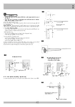
E1
1
2
1
E2
E3
E4
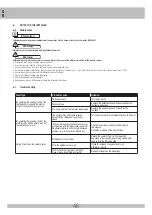
3.5.2 Checking the motion
Warning
!
• When the mounting is completed, neutralize the hydraulic lock (if present in the operators)
by turning the correct key through 180° counter-clockwise, and move the gate-leaves
manually to check on the smoothness of the movement; this should be done very slowly,
otherwise the operators will take in air and, consequently, will have to be bled.
• Open and close the gate leaf to check that the operator can move freely without rubbing
and without going against either the gate leaf or the gate post.
• After making the checks, reset the hydraulic lock by turning the release key fully in a
clockwise direction.
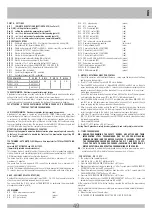
3.5.3 Electrical connection
Make the electrical connection according to the wiring diagram (
D1
) - see paragraph “System
electrical connection”.
Connect the supplied capacitor (
B4
pos.
12
) to the electric control unit according to the wiring
diagram of the unit itself.
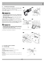
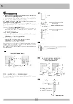
3.5.4 Fitting the protection casing and removing the bleed screw
Fit the protective casing (
E1
pos.
1
) to rod and insert into the operator.
Hold the casing bottom (
E2
pos.
2
) in position with a cross-head screwdriver (
E2
pos.
3
).
Fit the push-on cover (
E3
pos.
2
) on to the protective casing (
E3
pos.
1
).
Tighten the fixing screw of the protective casing (
E4
pos.
1
).
On completion of the assembly, remove the bleed screw (
E5
pos.
4
) using a CH7 hexagonal wrench.
G
B
Summary of Contents for IDRO C 27/1B
Page 74: ...74 ...

