background image

82

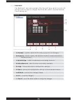
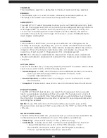
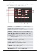
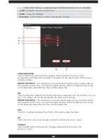
CHANNEL

The CHANNEL selection is defaulted to channel 1 and cannot be selected.

ENABLE

The ENABLE option is used to enable (checked) and disable (default, un-

checked) motion detection event recording and notifications. 

SENSITIVITY 

The SENSITIVITY select drop down allows you to set the motion detection 

sensitivity level. This sets the motion sensitivity level for motion detection 

which controls all recording and alerting functions when applicable.  To set the 

sensitivity level for your IPcam-SD, move your cursor over to the drop down 

arrow and left click it to display the options available. The sensitivity level 

ranges from Lowest, Lower, Middle (default), High, Higher, and Highest. 

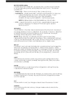
AREA DETECT 

The AREA DETECT position button allows you to set the area masking for 

motion detection.  Simply use the left mouse click and hold and then drag 

diagonally up or down to select and de-select the masking areas.  The area of 

masking will displayed as light sky blue and the non masking area will show the 

camera image.  Click OK to confirm or CANCEL to cancel area detection setup.

NOTE: 

Muliti location masking can be used within the camera image. 

SCHEDULE 

The SCHEDULE button lets you set up to 4 different recording periods for 

each day of the week.  By doing this, you can create schedules that will allow 

you to schedule when the IPcam-SD should start and stop implementing 

motion detection recording, thus saving space and the amount of unwanted 

recordings that would be generated during a 24hr manual recording.  

NOTE: 

This schedule is dedicated for video motion detection schedule when 

motion detection should be on or off, not related to the schedule used in video 

and snapshot.

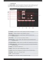
ACTION AREA

The ACTION AREA lets you specify what the IPcam-SD should do when a 

motion detection event occurs and consists of the following option:

•  Alarm Output

 – enables the IPcam-SD’s alarm output device that is 

              connected to the I/O terminal (output terminal supports 
              5VDC) to come on when motion occurs.

•  Record Channel

 – enables video recording to save to the MicroSD card of 

              the IPcam-SD.

•  Snapshot

 - enables photo snapshots to save to the MicroSD card of the IPcam-SD..

PTZ ACTIVATION

The PTZ ACTIVAION button lets you select the tour/preset that you would 

like to use when ever motion has been detected. This feature also consists of 

a DELAY (post-movement) time frame that lets you dictate how much longer 

the IPcam-SD should keep touring after its default 10 second (per motion 

detection event) recording has expired.  

NOTE: 

To use PTZ Activation for Preset and Tour, be sure to pre-set the Preset 

positions and preset the Tour positions in the “PTZ” section of the CMS software.

Summary of Contents for IPCAM-SD

Page 1: ...IPcam SD User s Manual WiFi Security Camera for Smartphone Tablet and Computer ...

Page 2: ...just the product or put it in another place Extend the distance between the equipment interfered and the product Refer to dealers or experienced radio electrician for help Warranty SecurityMan Inc warrants that this product will be free from defects in title materials and manufacturing workmanship for one year or otherwise specified on the product packaging This limited warranty shall commence fro...

Page 3: ...d Setting Basic Settings Device List Schedule Type Selector Plan Template Window Schedule View Version Info IPCAM CMS Account Group Add Group Delete Group Group List Group Rights List User User Account Window Add User Delete User Modify PW Password Local Log Log Type Operation Alarm Begin Time End Time Detail Screen Search Next Page Pre Page Log Export Add Remove IPCam Area List Add Area Add Devci...

Page 4: ...rvice IP Filter DDNS Email NTP Network Time Protocol ARSP Mobile Monitor UPnP FTP Real Time Streaming Protocol Cloud GUI Display CAM Name Anti Jitter Transparency Area Masking Date Time Stamp Camera Name Position Mirror Image Flip Image Anti Flicker IRSwap Advanced SD Card Manage Read Write Snapshot Format Disk Partition IPCam CMS Account Modify User Modify Group Modify PW Password Add User Add Gr...

Page 5: ...rd live video remotely from almost anywhere where you have access to a computer web browser and broad Internet connection Wired or wireless The IPcam SD can be accessed through a wired connection using the 10 100 RJ45 connector It also supports wireless 802 11 b g n as well as WEP WPA and WPA2 encryption Notifications Receive email notifications to your email account when an alarm is triggered It ...

Page 6: ...shock during subsequent use DO NOT place this product too close to medical equipment 1 This product may cause medical equipment to malfunction 2 Place the product at least 22cm from the heart pacemaker Radio waves can potentially influence the pacemaker and can lead to respiratory disturbance DO NOT use this product to infringe on one s privacy spying intercepting and related activities are illega...

Page 7: ...e temperature or humidity may change rapidly Keep it dry dustless and avoid lens exposure in direct sunlight Keep product away from heat sources such as electric heaters Do not use the camera near harmful chemicals Do not place product near any strong magnetic objects It might influence the normal operation of the product if used at the fringe range of normal temperature Please turn off the power ...

Page 8: ...cket IPcam SDX2 screws CD PC software and manual IPcam SD 2 x IP cameras IPcam SDX2 Quick Start Guide I O terminal 1 IN 1 OUT 2 x I O terminals IPcam SDX2 Ethernet cable 2 x Ethernet cable IPcam SDX2 Power adapter 2 x Power adapters IPcam SDX2 Antenna 2 x Antennas IPcam SDX2 ...

Page 9: ...one Rear View Bottom View Mounting Hole Reset Button Base NOTE The reset button located at the bottom of the camera is used to reset the IPcam SD to its original factory default settings To apply power up your camera then press and hold in the reset button using a small non pointed non metallic instrument paper clip or other stationary for 5 seconds ...

Page 10: ...ernet cable provided connect one end into the Network port of the camera and the other into your network router switch 4 Power up the camera by plugging in the cameras power adapter 5VDC 2 0A into the power socket located on the back of the IPcam SD and the other end into a power outlet NOTE The IPcam SD will perform a 30 second self test every time it is powered up This test will include the head...

Page 11: ... you select Login your camera screen will be displayed immediately 2 Begin by opening Internet Explorer and going to http www xmeye net fig 1 1 Select Register and input your information into the available fields fig 1 2 NOTE Username E mail and Password are required fields Fig 1 1 Fig 1 2 Phone Setup ...

Page 12: ... is the serial ID of the IPCam which you can obtain by scanning the QR Code located on the device please refer to the QSG for instructions on how to scan the QR Code Provide a Device Name for your device fig 1 5 Note Username is admin and the password is left blank 7 With the device being registered to your XMEye account you may use your phone to login By User and the registered device will automa...

Page 13: ...ew 1 This method is used to add your IPCam without registering your user information There are numerous ways to add view your IPCam under By Device QR Code Search in LAN and Address 2 Serial QR Code Please refer to the Quick Start Guide 3 Search in LAN A Make sure that your phone is connected to the same router as the IPCam B Begin by pressing Add and selecting the Search in LAN button fig 2 1 C Y...

Page 14: ...the four quadrants B Play Stop Icon Record Icon Delete Channel Icon Alarm Icon Snapshot Icon Microphone Icon C IPCam Live App Settings Icon Gives you access to change the settings for the IPCam Live application Swipe Left Right Screen Icon Indicates you can swipe to the left for more options ...

Page 15: ...applicable for IPCam G Close Far You can zoom up to a specific section of the camera Not applicable for IPCam H Aperture Configure the opening of a lens s diaphragm through which light passes Not applicable for IPCam I Camera Settings Configure settings for any specific devices you have connected to your phone Settings include but not limited to wifi setup remote playback video motion alarm settin...

Page 16: ... Setting Changes the quality of the video resolution frames per second bitrate etc 6 SD Card Info Displays information on the SD card Formats the SD Card and configures the overwrite function 7 Alarm Setting Configures video motion alarm input and output snapshots recording and email function Any recorded videos or snapshots from your phone will be displayed here You can play the videos pictures f...

Page 17: ...re saved onto the SD card in the IPCam You may select through the date time and type of recorded files i e Motion recording snapshots video blind etc You can view the IPCam snapshots which were taken on the IPCam app You can save the snapshots onto your phone s photo gallery or delete them ...

Page 18: ...t Help Configures the settings for the IPCam application on your phone Configurations include alert sounds audio video ratio wifi network etc Information on the IPCam application and contact information are located on this page ...

Page 19: ...ange with noticed 3 The CMS Central Management Software Setup screen will appear as shown below Select Yes in the User Account Control window and then click Next to continue or Cancel to cancel the installation Software CMS Installation System Requirements Operating System Windows XP Vista 7 and 8 32 bit 64 bit OS Processor Intel Pentium 4 2 0GHz or above Video Card NVIDIA GeForce 6800 equivalent ...

Page 20: ...t installing the CMS to your computer recommended as illustrated above 7 Click Next in the Ready to Install window and then click Finish to complete the CMS software installation as shown below NOTE When you first launch the central management software you will be prompted with a pop up stating that your device list is empty please add a device Click OK to proceed 8 After the installation is compl...

Page 21: ...dow will appear as shown below click on OK to continue NOTE The default User Name is super password leave blank 2 At the CMS main screen click on System and then Add Remove IPCam to open the device manager window to configure as illustrated below 3 In Add Remove IPCam window click on ADD AREA to open the Zone window as illustrated above The zone could be the location where the IPcam SD camera is i...

Page 22: ...ttings on your computer click Start All Programs Accessories Command Prompt At the DOS Command Prompt screen type ipconfig and then press Enter as illustrated below Please write down your local IPv4 Address or the IP address the Subnet Mask and the Default Gateway Exit from the Command Prompt window by typing exit 8 Go back to the EditDevice window to change the Subnet Mask and Default Gateway to ...

Page 23: ...ch button to re scan for the IPcam SD addresses as illustrated below Then click on the new IP address Ethernet to make the change and then click the OK button to confirm the change and to go back to the Add Remove IPCam window Click OK again to go back to main CMS window CMS Quick Connect Intranet 1 In the main CMS screen double click on the IP address and then double click on CAM01 to connect to ...

Page 24: ...s click Browse to choose a different destination folder Next select the Record Setting and make sure Overwrite is checked and then select the disk partition you want save the video picture files as illustrated below Click Apply or OK to confirm the changes and click to go back to main CMS screen 4 To start recording right click on camera image and choose Local record as illustrated below ...

Page 25: ...mera s selected from the Device Display Area C Horizontal Expand Clicking on the HORIZONTAL EXPAND will hide the device display area giving you a wider look at the live feed from your camera D Multi Screen View The MULTI SCREEN VIEW area allows you to partition the live view screen according to the amount of channels cameras you want to monitor Options include 1 4 6 8 9 16 25 36 64 and View Full f...

Page 26: ...els Audio Enables Disables sound for the selected channel Local Record Starts manual recording for the selected channel all recordings are stored to the local computer Check System PC Config for local storage directory Zoomed Enables Disables the digital zoom feature Once zoomed is selected left mouse click and drag on the camera image for digital zoom uncheck zoomed for normal camera view Snapsho...

Page 27: ...es such as PTZ Controls Color Adjustment IPcam SD and CMS configuration and Playback The menu area consists of the following NOTE The area above the MENU area will change to correspond with options that are related to the menu option selected For example the image shows PTZ controls because PTZ was selected from the menu area PTZ System Logout Color Playback ...

Page 28: ...rrows The NAVIGATIONAL ARROWS allow you to move your camera in the corresponding direction when you click them giving you a full 360 degree horizontal motion and 120 degree vertical motion for pan and tilt To zoom you can single click for stop and go motion or click and hold for a continuous pan B Speed bar The SPED BAR allows you to set change the current speed rate 8 speed levels ranging from fa...

Page 29: ...nging the position of the camera To add a preset point first move the IPcam SD to the desired location choose the Preset number and click the to add it or use the icon to delete it To pan to preset position simply select the preset number and then click on the Goto button E Tour The TOUR bar is used to create an automatic camera rotation movement based on the preset points positions you created To...

Page 30: ...d to adjust the cameras brightness level B Contrast The CONTRAST adjustment bar is used to adjust the cameras contrast level C Saturation The SATURATION adjustment bar is used to adjust the cameras saturation level D Hue The HUE adjustment bar is used to adjust the cameras hue level E Default The DEFAULT option applies all the color settings to their factory defaults All brightness contrast satura...

Page 31: ...ace screen located on the bottom right hand corner of the screen Once selected the the system control screen will pop up providing you with the following options A PC Config consists of basic CMS network and recording settings B IPCam CMS Account used to manage CMS users and rights C Local Log used to view CMS event logs D Add Remove IPCam used to add remove cameras to from the CMS E IPCam Config ...

Page 32: ...r to click the APPLY button located at the bottom of each tab to save your changes and click on the X located at the top right corner of the screen exit A Base Config CMS recording configuration B Alarm Setting CMS alarm configuration C Record Settings Allows you to program the IPcam SD to record on specific days and times D Version Info Displays detailed device information ...

Page 33: ...l record and operate These categories are A Log Maintenance IPcam SD alarm log configuration B Snapshot snapshot file path and format settings C Local Record event recording file path configuration D Device used to configure the cameras start up options E Sync Time With PC schedule date time sync configuration F Start Up CMS startup configuration ...

Page 34: ...ing its contents Save alarm log consists of 7 15 and 30 default days to save the log files SHOW ALARM LOG The SHOW ALARM LOG option allows you to enable default disable the real time alarm events that are displayed in the Operation Log Window of the CMS interface SAVE OPERATION LOG DAY The SAVE OPERATION LOG DAY feature allows you to specify how long of an operation log the CMS should keep before ...

Page 35: ...on your computer that you would like to store the snapshots that are taken To use this feature simply click on the BROWSE button located to the right of the current destination description to make your selection We recommend to use the default directory C Program Files CMS Picture for snapshots PICTURE FORMAT The PICTURE FORMAT feature allows you to specify the type of file format bmp default or j...

Page 36: ...ecorded events to RECORD DIRECTORY The RECORD DIRECTORY feature allows you to specify the location on your computer that you would like to store the recorded events To use this feature simply click on the BROWSE button located to the right of the current destination description to make your selection We recommend that you use the default directory C Program Files CMS Record to record events ...

Page 37: ...list if you have more than 2 IPcam SD listed in the same zone the default setting is unchecked SINGLE SCREEN MAIN STREAM MULTI SCREEN EXTRA STREAM The SINGLE SCREEN MAIN STREAM MULTI SCREEN EXTRA STREAM option will automatically use Main Stream for all single channel live views and Extra Stream when ever viewing multiple screen or more than single full screen view This option is checked by default...

Page 38: ...ed on the Base Config tab allows you to specify how often the CMS should update its date time by synchronizing with your computer date and time The options available are Never default Everyday Every Son Every Mon Every Tue Every Wed Every Thu Every Fri Every Sat ...

Page 39: ...quired Before Exiting Auto Login START UP The START UP area located on the Basic Config tab consists of 7 settings that are used to configure the actions to be taken every time both the computer and the CMS are initiated These settings are LANGUAGE The LANGUAGE drop down allows you to select the preferred language to be used for the CMS These options include ...

Page 40: ...WITH THE LAST MONITORING CHANNEL feature allows the CMS software to automatically start up with displaying the same live feed s that were being monitored when the CMS was shut down close exit The system default is enabled AUTOMATIC LOCK SCREEN The AUTOMATIC LOCK SCREEN feature allows the CMS to automatically lock the screen prompting the user to enter his hers password in order to use the software...

Page 41: ...O Trigger used configure alarm Input Output related features B Video Motion used configure Motion Detection alarm features C Video Blind used configure Video Camera Blind alarm features D Device Disconnect used configure Device Disconnect related alarm features NOTE Please remember to click the APPLY button located at the bottom of each tab to save your changes and click on the X located at the to...

Page 42: ...er of the screen exit A Device List used to select which device you want to configure B Camera Mapping camera to I O mapping Map the IPcam SD right side to the Alarm Input Mapping left side by selecting CAM1 and Add C Alarm Enable enables the CMS to monitor I O alerts D Alarm Sound enables disables audible alert notification E Sound File Path used to specify the location of the sound file you want...

Page 43: ...feature simply click on the BROWSE button located to the right of the current destination description to make your selection FULL CH DISPLAY The FULL CH DISPLAY check box will allow the CMS to display the triggered channel in a Single Channel Full Screen for the set time frame when alarm I O occurs DISPLAY TIME The DISPLAY TIME edit box is use to specify how long in seconds the CMS will display th...

Page 44: ...40 ...

Page 45: ...s the CMS to monitor video motion alerts C Alam Sound enables disables audible alert notification D Sound File Path used to specify the location of the sound file you want to use E Full CH Display enables disables Single Channel live view for the camera being triggered F Display Time full channel display time configuration NOTE Please remember to click the APPLY button located at the bottom of eac...

Page 46: ...ert that can be heard from your computer whenever an alarm is triggered SOUND FILE PATH The SOUND FILE PATH feature allows you to specify the location on your computer of the audible alert tone that you would like to be played whenever an event is triggered To use this feature simply click on the BROWSE button located to the right of the current destination description to make your selection FULL ...

Page 47: ... remember to click the APPLY button located at the bottom of each tab to save your changes and click on the X located at the top right corner of the screen exit A Device List used to select which device you want to configure B Video Blind Enable enables the CMS to monitor video blind alerts C Alarm Sound enables disables audible alert notification D Sound File Path used to specify the location of ...

Page 48: ... Blind is enabled and an event occurs the system will only record video footages no picture snapshots will be taken ALARM SOUND The ALARM SOUND enables disables the audible alert that can be heard from your computer whenever an alarm is triggered SOUND FILE PATH The SOUND FILE PATH feature allows you to specify the location on your computer of the audible alert tone that you would like to be playe...

Page 49: ...u want to use NOTE Please remember to click the APPLY button located at the bottom of each tab to save your changes and click on the X located at the top right corner of the screen exit DEVICE LIST The DEVICE LIST displays all the devices IPcam SD that are configurable by the CMS and currently established connection ALARM SOUND The ALARM SOUND enables disables the audible alert that can be heard f...

Page 50: ...s that will allow you to program the CMS to set overwrite option recording file length alarm file length select storage disks record on specific days times and event types These categories are A Basic Settings basic record settings B Device List used to select which device you want to configure C Schedule Type Selector used to select the type of plan to use D Plan Template Window used to select an...

Page 51: ... will be stored in a folder called Record under the selected storage drive or DISK LIST below DISK LIST The DISK LIST area displays all the partitions hard drives that are available for you to select as the CMS main recording partition DISK LIST displays the total size of the disk the number of megabytes used the number of megabytes free and the disk space available for recording Please note that ...

Page 52: ...am SD should record and the type of recording that should be implemented during the set schedule Regular Detect Alarm thus saving space and the amount of unwanted recordings that would be generated during a 24hr manual recording implementation Located on the Plan Template area is an Edit Template button which will allow you to edit and create template settings as needed Please note that there are ...

Page 53: ...he Record Setting tab lets you edit any of the pre configured plan templates and even create a new one based on your requirements To begin click on the Edit Template button using your mouse to bring up the PLAN TEMPLATE SCREEN as shown in the images below ...

Page 54: ...time frame D Detect enables motion detection for the set period time frame E Alarm enables alarm activated recording for the set period time frame F Plan Template Window displays all templates that have been created G Add used to create a new plan template H Modify used to modify an existing plan I Delete used to delete an existing plan that is no longer needed NOTE Please remember to click the OK...

Page 55: ...K LIST inside the Record folder under the sub folder MotionRecord ie C Record MotionRecord folder NOTE The Detect scheduled recording are accountable for Video Blind recording All video blind event recording will also be stored in the MotionRecord folder ie C Record MotionRecord folder ALARM The ALARM check box enables disables Alarm I O triggered recording throughout the set time period All Alarm...

Page 56: ...m the Plan Template Window and click the Delete button to delete it SCHEDULE VIEW The SCHEDULE VIEW area is used as a visual map of the CMS s current recording schedule VERSION INFO The Version Info or CMS version tab located in the PC Config settings displays specific CMS device information This information includes Video 1 0 0 5 factory use only Decoder 2 3 0 16 factory use only Device Config 2 ...

Page 57: ...users with CMS Account rights can add create or modify these settings The 2 tabs located on the CMS Account window are NOTE The IP Cam CMS Account settings only pertain to users who are able to access and use the CMS software only not IPCam users 1 Group Used to create user rights groups that can be applied to newly created users 2 User Used to create CMS user accounts ...

Page 58: ...hat will let you create user groups with specific rights privileges that can be applied to newly created users These options are A Group List displays all the groups available B Add Group used to create a new group C Delete Group deletes the selected group D Group Rights list group privileging ...

Page 59: ...ill be prompted to provide a name and description of the new group when selected DELETE GROUP The DELETE GROUP button allows you delete any of the groups that you no longer need NOTE The Administration group is created by default and cannot be deleted nor modified GROUP LIST The GROUP LIST displays all the groups that have been created GROUP RIGHTS LIST The GROUP RIGHTS LIST window allows you to e...

Page 60: ...and features RECORD SETTING The RECORD SETTING right allows users to create and change scheduled recording settings IPCAM CONFIG The IPCAM CONFIG right gives users access to the IP camera configuration menu option LOCAL LOG The LOCAL LOG right allows users to access and view the CMS system logs as needed IPCAM CMS ACCOUNT The IPCAM CMS right gives users permission to access the CMS Account menu wh...

Page 61: ... WINDOW The USER ACCOUNT WINDOW displays all the all the users that have been created under different groups or rights ADD USER The ADD USER button allows you to create new CMS user accounts To create a new user click on the Add User button to bring up the User window as shown in the image below The new user window will allow you to select the user group you want the user to be associated with and...

Page 62: ...o confirm or CANCEL to cancel NOTE The Super user account is created by default and cannot be deleted nor modified The system default password is blank for Super account MODIFY PW The MODIFY PW modify password option allows you to change the selected users password by entering the current password followed by the new password and a confirmation of the new password Click OK to accept or click CANCE...

Page 63: ...ws you to choose the event type to look in B Operation Alarm drop down allows you to select a specific event type to look for C Begin Time used to specify a specific start date time to search between D End Time used to specify a specific end date time to search between E Detail Screen displays the event log F Search initiates the log search G Next Page displays the next page of log events H Pre Pa...

Page 64: ... to display the calendar To adjust the time click the value you wish to change and click on the up down arrows to increase or decrease its value when highlighted END TIME The END TIME drop down menus allows you to set up a specific end date time search parameter that you wish to view the log for To adjust the date simply click on the drop down arrow to display the calendar To adjust the time click...

Page 65: ...mp to the next page in the event log For example the event log detail screen will only display 34 events per page therefore in order to get to the next page you would have to click on the NEXT PAGE button to view the next set of 34 events PRE PAGE The PRE PAGE button will jump to the previous page in the event log LOG EXPORT The LOG EXPORT option initiates the save as backup process which will cop...

Page 66: ... displays all the cameras that have been added to the CMS 2 Add Area used to add an area 3 Add Device used to add a IPcam SD 4 Modify used to modify area a camera connection settings 5 Delete deletes devices from the CMS 6 Import Config imports saved device and area settings 7 Export Config saves the current camera area settings 8 Connection Test IPcam SD connection test ...

Page 67: ...re or add a device to ADD AREA The ADD AREA option will allow you to join your IPcam SD cameras into groups to help keep your security system organized For example you can create a group called HOME and add child groups called downstairs for all cameras monitoring the 1st floor of a home and one called upstairs for all cameras monitoring the 2nd floor of a home ...

Page 68: ...IP Search initiates the find device feature C Device Name allows you to manually name your IPcam SD D Login Type used to specify the cameras login protocol E IP Address cameras identification number that lets it be found over the Internet F Port lets you specify the dev port to be used G User Name user name password that you assigned to the camera H Zone zone that the camera will be added to I Edi...

Page 69: ... Cloud or Serial ID type of connection The serial ID can be found under IPCam Config Info Version of the CMS software IP ADDRESS The IP ADDRESS edit box allows you to manually input the IP address that you have assigned for the IPcam SD when installing the CMS software on a device outside your network since using the IP SEARCH feature will be unable to locate your camera outside your network The I...

Page 70: ...shown below Input the Serial ID into the Serial ID field setup the User Name Password and Zone to comply as instructed above NOTE When using serial ID for Cloud it is not required to open ports from you router however UPnP is required to be enabled in your local router EDIT DEVICE The EDIT DEVICE option is used to save any changes that were made to the selected camera from the Device List Window T...

Page 71: ...ou are unsure as to what IP address Subnet Mask and Gateway to use or reference our QSG Quick Start Guide to obtain an IP address ADD DEVICE The ADD DEVICE option adds the selected configured device to your CMS Area List EXAMPLE HOW TO ADD THE IPCAM SD TO THE CMS The first thing you need to do is create a group Highlight Zone List in the device list area and click on the ADD AREA button to bring u...

Page 72: ...68 Next make sure your IPcam SD is connected to your network and turned on Select the area you created HOME and click on the ADD DEVICE option to bring up the EDIT window as shown ...

Page 73: ...ge below NOTE The default IP address given to the IPcam SD when connected via the Ethernet cable wired is 192 168 1 10 and 192 168 1 11 when connected over a wireless network WiFi Using your mouse click on the IP Address that represents your IPcam SD and click on the ADD DEVICE button to add the camera to the HOME group that you created ...

Page 74: ...70 Click OK to close the EDIT window and click ok once more to close the Add Remove IP Camera window as illustrated ...

Page 75: ...sired profile name and then click on the delete icon IMPORT CONFIG The IMPORT CONFIG option allows you to restore the saved bin profile settings back to the CMS software To import CMS configuration simply click on the IMPORT CONFIG button browse for the bin file saved in your local directory and then click OPEN EXPORT CONFIG The EXPORT CONFIG option allows you to back up or save the bin profile se...

Page 76: ... will operate and be controlled The IPCam Config section consists of the following sections 1 Device List displays all the devices that are controlled by the CMS 2 Sub Menu Icons displays all the sub menu options available for each of the Main Menu options selected 3 Main Menu Icons displays all the menu options available in the IPCam Config NOTE You will be prompted to select a device from the de...

Page 77: ...t can be configured through the CMS NOTE You will be prompted to select a device from the device list in order to view the IPCam Config options SUB MENU ICONS The SUB MENU ICONS area displays all the sub menu options available for each of the Main Menu options selected ...

Page 78: ...e options include 1 Record Playback Used to set up the IPcam SD s video and photo recording parameters 2 Alarm Used to set up the IPcam SD s alarm parameters 3 System Used to configure the IPcam SD s network and device parameters 4 Advanced Used to configure advanced IPcam SD parameters 5 Info Used to view memory and version information ...

Page 79: ...menu located in the IPCam Config settings allows you to configure the IPcam SD s video and snapshot recording parameters and consists of the following 2 sub menus 1 Video Video recording configuration 2 Snapshot Photo snapshot configuration ...

Page 80: ...ct which camera you want to configure B Recording Duration used to specify the length of each recording segment C Record Type used to implement a recording structure D Schedule Area used to setup a recording schedule E Copy copies the current configuration settings F Paste pastes the configuration settings to the selected camera G OK saves the changes H Cancel exits the menu without saving the cha...

Page 81: ...schedule will not be taken into effect if there is a schedule set under the video motion settings Manual enables 24 hour video recording None disables manual recording SCHEDULE AREA The SCHEDULE AREA lets you set up to 4 different recording periods for each day of the week By doing this you can create schedules that will allow you manipulate when the IPcam SD should start and stop record thus savi...

Page 82: ...u want to configure B PreSnap used to specify the amount of photos to be taken when an event occurs C Record Type used to implement a recording structure D Schedule Area used to setup a recording schedule E Copy copies the current configuration settings F Paste pastes the configuration settings to the selected camera G Refresh restores any changes made H OK saves the changes I Cancel exits the men...

Page 83: ... lets you set up to 4 different recording periods for each day of the week By doing this you can create schedules that will allow you manipulate when the IPcam SD should start and stop taking snapshots thus saving space and the amount of unwanted photos that would be generated during a 24hr manual implementation Located on the Schedule Area is a Day drop down option which will allow you to select ...

Page 84: ...ecording parameters and consists of the following 6 sub menus 1 Video Motion Motion detection configuration 2 Video Blind Video blind configuration 3 Alarm Input Alarm I O configuration 4 Alarm Output Alarm output configuration supporting up to 5VDC output devices 5 Abnormal Camera malfunction alert configuration ...

Page 85: ...el D Schedule used to setup a recording schedule E Action Area used to control what the IPcam SD should do when an event occurs F PTZ Activation enables motion activated tour and preset movement G Notification Area used to select how you want to be notified when an event occurs H Interval motion detection delay time to record I Delay post Record time frame J Copy copies the current configuration s...

Page 86: ...ach day of the week By doing this you can create schedules that will allow you to schedule when the IPcam SD should start and stop implementing motion detection recording thus saving space and the amount of unwanted recordings that would be generated during a 24hr manual recording NOTE This schedule is dedicated for video motion detection schedule when motion detection should be on or off not rela...

Page 87: ...ill be subtracted from the Pre Record time frame The system default setting is interval 1 second the earliest the system can start to record on an event To extend the event start time to record please set to a higher value DELAY The DELAY post record time frame lets you dictate how much longer the IPcam SD should keep recording after its default 10 second per motion detection event recording has e...

Page 88: ...tection sensitivity level D Schedule used to setup a recording schedule E Action Area used to control what the IPcam SD should do when an event occurs F PTZ Activation enables motion activated tour and preset movement G Notification Area used to select how you want to be notified when an event occurs H Delay post Record time frame I Copy copies the current configuration settings J Paste pastes the...

Page 89: ...The ACTION AREA lets you specify what the IPcam SD should do when a blind event occurs and consists of the following option Alarm Output enables the IPcam SD s alarm output device that is connected to the I O terminal output terminal supports 5VDC to come on when video blind occurs Record Channel enables video recording to save to the MicroSD card of the IPcam SD Snapshot enables photo snapshots t...

Page 90: ...l recording will not stop until 5 00 35 pm 10 second default 15 second delay COPY The COPY button can be used to copy the current configuration on the screen to the other cameras available through the CMS when more than one camera is available PASTE The PASTE button is used to paste the configuration settings that were copied to the selected camera REFRESH The REFRESH button discards the changes y...

Page 91: ...control what the IPcam SD should do when an event occurs E PTZ Activation enables alarm input activated tour and preset movement F Notification Area used to select how you want to be notified when an event occurs G Type used to select the type of I O protocol to be used H Interval alarm input delay time to record I Delay post Record time frame J Copy copies the current configuration settings K Pas...

Page 92: ...oSD card of the IPcam SD PTZ ACTIVATION The PTZ ACTIVAION button lets you select the tour preset that you would like to use whenever an alarm input occurs This feature also consists of a DELAY post movement time frame that lets you dictate how much longer the IPcam SD should keep touring after its default 10 second per camera failure event recording has expired NOTE To use PTZ Activation for Prese...

Page 93: ...r its default 10 second per camera failure event recording has expired For example if a camera failure event occurs at 5 00 00 pm and you have the delay time set to 15 seconds the actual recording will not stop until 5 00 35 pm 10 second default 15 second delay COPY The COPY button can be used to copy the current configuration on the screen to the other cameras available through the CMS when more ...

Page 94: ...ices that has higher power rating or self powered output devices may not be supported ON The ON check box enables the IPCam SD alarm output device to be active or stay on 24 7 This option will not be related the the alarm input setting IMPORTANT NOTE The output port is pin 3 and 4 please use an output device that supports 5VDC only Using other output devices that has higher power rating or self po...

Page 95: ...hout saving the changes EVENT TYPE The EVENT TYPE drop down is used to select which monitoring function you wish to enable and consists of the following options SD Card Not Found sends an alert when the IPcam SD cannot locate the SD card Insufficient Memory sends an alert when SD card does not have enough space for recording based on the percentile setting under the Less Than option SD Card Un Rea...

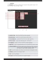
Page 96: ...Service Network services configuration 5 GUI Display Camera configuration SHOW LOG The SHOW LOG option is used to enable checked and disable un checked monitoring events to be saved in the system log file REFRESH The REFRESH button discards the changes you made to the current settings and sets them back to the way they were when the configuration window was first opened OK The OK button saves your...

Page 97: ...he IPcam SD s time format E Language used to set the IPcam SD s display language F HDD Full used to enable disable the overwrite feature of the SD card G Video Standard NTSC PAL video format Please use NTSC for North America PAL for European counties please check your local listing for video standards used H DST used to enable and configure the IPcam SD for daylight savings I Refresh restores any ...

Page 98: ...ns include 12 HOUR 24 HOUR LANGUAGE The LANGUAGE drop down lets you change the language of the IPcam SD s menu It is important that you stay away from making changes unless you are really sure that you want to change the language Having the menus in a foreign language can make it difficult to navigate through the options to try and get back the right one The options available are English Spanish F...

Page 99: ...he STANDARD to PAL European move your cursor over to the drop down arrow and left click it to display the options available DST The DST option allows you to set up the IPC SD to automatically update its time according to your geographic daylight savings requirements REFRESH The REFRESH button discards the changes you made to the current settings and sets them back to the way they were when the con...

Page 100: ...64 compression not configurable C Resolution resolution configuration D FPS frames per second configuration E Bit Rate Type Constant or Variable Bit Rate selection F Quality lets you define the quality of the video being recorded only available when VBR is selected the Bit Rate Type G Bit Rate kb s video bitrate configuration only available when CBR is selected the Bit Rate Type H Frame Interval s...

Page 101: ...otage quality but takes less hard drive space and faster video streaming NOTE The FPS ranges from 1 30fps the system default setting for main stream is 30fps and the default for extra stream is set at 15fps BIT RATE TYPE The IPcam SD supports two bit rate types CBR and VBR CBR stands for Constant Bit Rate which means the DVR will always use the bit rate Kb S setup under the Bit Rate setting below ...

Page 102: ...e intervals per second VIDEO AUDIO The VIDEO AUDIO option is used to enable default checked and disable un checked audio or video for the selected stream type Main Extra NOTE The audio must be checked system default to listen in on the IP camera from your CMS software To listen in on the IP camera check this option and then right mouse click on the camera image of the GUI and then select Audio SNA...

Page 103: ...ets you manually input the networks default gateway E Primary DNS used to input your networks primary DNS address F Secondary DNS used to input your networks secondary DNS address G Media Port lets you specify which port to use for the IP camera H Remote Access Full Bandwidth enables disables full bandwidth dedication I Remote Access Priority used to select your connection preference priority qual...

Page 104: ...s disables the Dynamic Host Configuration Protocol which is a protocol used by a network server to dynamically assign IP addresses to networked devices We recommend that you assigned a local area network IP address to the IPcam SD over DHCP enabled The system default is set to unchecked IP ADDRESS The IP ADDRESS edit box allows you to manually input the IP address that you have assigned for the IP...

Page 105: ...t number that you have selected your router to use for the IPcam SD to be accessible over the internet The media default port is 34567 recommended port HTTP PORT The HTTP PORT edit box lets you specify the port number that you have selected your router to use for the IPcam SD to be accessible over the internet The HTTP default port is 80 Please change to other port such as 89 if you are having dif...

Page 106: ... to start searching for the wifi access point s or SSID in your network Click to highlight or select the known access point and then check Enable box Next input the wifi encryption password or passphrase and double check to make sure the IP address subnet mask and gateway are those of your local area network settings Click OK to confirm and exit out from the wifi set up window or CANCEL to cancel ...

Page 107: ...essing the camera B DDNS used to set up your DDNS account information for remote access C Email used to enable disable email alert notifications D NTP used to enable network time protocol to update and synchronize the date time E ARSP Not applicable for IPcam SD F Mobile Monitor used to enable disable mobile phones monitoring service G UPNP used to enable universal plug and play for Point to Point...

Page 108: ... listed allowed or black listed disallowed from accessing the IPcam SD remotely Double click on this option to bring up its corresponding configuration window as shown below Make sure to check Enable box select between black white list input the IP address to privilege and click Add Click OK to confirm the set up highlight and click DELETE button to delete the filter or click CANCEL to cancel IP f...

Page 109: ...ck OK to confirm set up or click CANCEL to cancel EMAIL The EMAIL service allows you to enable checked or disable default unchecked email alert notifications Double click on this option to bring up its corresponding configuration window as shown below When an event occurs the system will send you alert email with attached snapshot of the IPcam SD images To set up an email alert feature check the E...

Page 110: ... computers one computer to enable NTP service and the second computer running CMS software 1 To enable NTP service on computer 1 or server PC go to Control panel Administrative Tools Services Scroll to the bottom of services and double click on Windows Time In Windows Time select Automatic in the Startup type section and finally click Apply and OK to save the setting as shown below Jot down the IP...

Page 111: ...ver IP section leave the Port 123 default select the Time Zone according to your area for example California we select GMT 8 00 for the time zone and setup an update period system default is set to 10 minutes Click OK to accept the setting or CANCEL to cancel ARSP not applicable with IPcam SD model MOBILE MONITOR The MOBILE MONITOR service allows you to enable default checked or disable unchecked ...

Page 112: ...provide a directory name starting with a forward slash Click OK to confirm set up or click CANCEL to cancel NOTE The directory Name path for FTP cannot be blank and it has to start with a forward slash system default to start the recording directory 108 REAL TIME STEAMING PROTOCOL The REAL TIME STEAMING PROTOCOL enables the video footages to be able to live stream to any real time software player ...

Page 113: ...am connection and sdp is the command used in VLC player To connect using extra stream input value 1 instead of 0 NOTE Please noticed that the symbol is required in between all commands instructed above Command may varies depending on the type of real players type and version CLOUD The CLOUD service allows you to enable checked or disable unchecked cloud services meaning to setup remote access usin...

Page 114: ...us screen CANCEL The CANCEL button discards any changes made and exits back to the previous screen GUI DISPLAY The GUI DISPLAY sub menu located in the System menu option consists of 14 basic settings related to the IPcam SD s live view display These settings include ...

Page 115: ...osition button located to the right of the CHN NAME caption to bring up the chn name edit box NOTE The maximum alphabets and numbers can be up to 20 characters long ANTI JITTER The ANTI JITTER feature enables disables the IPcam SD s anti flicker option helps stabilize or prevent the shaking of the camera lens when the camera pan and tilt The system default setting is enable checked to disable unch...

Page 116: ... positioned anywhere on the screen by using the Position button IR SWAP The IR SWAP by default is unchecked Please check it in cases where the color of the images maybe degrading or fading away Checking it will ensure that the IR cutter used inside the camera are properly seated correctly ANTI FLICKER The ANTI FLICKER option allows video to be displayed smoother to prevent the camera image from fl...

Page 117: ...intenance controls etc These options include 1 SD Card Manage SD card management 2 IPCam CMS Account IP camera user account configuration 3 Maintenance Auto maintenance configuration 4 Default Apply manufacturer default settings 5 Import Export Loads and Saves the current configuration 6 Reboot Used to re boot the IPcam SD 7 Upgrade IPcam SD firmware upgrade ...

Page 118: ...g the changes DISPLAY WINDOW The DISPLAY WINDOW displays all the current partitions and types that are currently on the SD card being used in the IPcam SD The display windows consists of Index Disk Event Status and partitions information READ WRITE The READ WRITE option is used to convert the selected partition drive into a read write partition In order to be able to record video onto the SD card ...

Page 119: ... will pop up to confirm the operation please click OK to confirm or CANCEL to cancel NOTE It is highly recommended that you always format a newly installed micro SD card to insure that it is formatted to the cameras specifications During formatting the software may take a few minutes depending on the size of the SD card being formatted please be sure to wait until the formatting process is complet...

Page 120: ...ay window displays all active user accounts B Modify User used to modify the selected users rights C Modify Group used to modify group rights D Modify PW used to modify the selected users password E Add User used to add users to the IPcam SD s user account list F Add Group used to create new user groups G Delete User used to remove users from the IPcam SD s user list H Delete Group used to remove ...

Page 121: ...odify the users rights and group To authorized certain users rights simply place a check mark on the number associated with the authority Uncheck the number next to the authority to disable the rights for that particular user MODIFY GROUP The MODIFY GROUP option is used to modify previously created user groups Once selected a Group pop up screen will be displayed as shown below which will allow yo...

Page 122: ...ase elect the user name you want to modify type in the old password type in the new password and confirm the new password click OK to accept or CANCEL to cancel NOTE Changing the password here in the modify pw section will not automatically changes the password in the device list under the Add Remove IPCam section You will need to also advanced to the Add Remove IPCam and change the password to ac...

Page 123: ...he image below The add user widow will allow you to select the user group you want the user to be associated with and also allow you to create the user name and user password for the account Click the OK button when you are done and the new user will be visible in the user account window NOTE You can apply individual rights to each user once the user s group has been selected ...

Page 124: ... USER The DELETE USER button allows you delete any of the users that you no longer need To delete a user simply click to highlight the user account and then click on the Delete User button DELETE GROUP The DELETE GROUP button allows you delete any of the groups that you no longer need To delete a group simply click to select a group from the drop down menu and then click on the Delete button NOTE ...

Page 125: ...AM REBOOT consists of 2 drop down menus that let you specify when you would like the IPcam SD to restart itself The first drop down is used to specify the day and the second drop down is used to specify the time for the IPcam SD to run maintenance system reboot The system default setting is set to Never A IPCam Reboot restarts the camera at the set date B Delete Files SD deletes old files C Refres...

Page 126: ... you want the files to be deleted REFRESH The REFRESH button discards the changes you made to the current settings and sets them back to the way they were when the configuration window was first opened OK The OK button saves your changes and exits back the previous screen CANCEL The CANCEL button discards any changes made and exits back to the previous screen DEFAULT The DEFAULT configuration sub ...

Page 127: ...UI Display and click on OK button to restore all GUI Display settings back to the manufacturer default settings F Encode Place a check mark on Encode and click on OK button to restore all encode settings back to the manufacturer default settings G Alarm Set Place a check mark on Alarm Set and click on OK button to restore all alarm set settings back to the manufacturer default settings H Net Servi...

Page 128: ... restore them when needed To export the system configuration click on the Export cfg button and then click on OK to start exporting OK The OK button saves your changes and exits back the previous screen IMPORT EXPORT The IMPORT EXPORT sub menu located in the Advanced menu option consists of 3 options that are used to save and restore your current IPcam SD s current configuration settings These opt...

Page 129: ...se this option to reboot the camera as shown below UPGRADE The UPGRADE sub menu located in the Advanced menu allows you to manually perform firmware and software upgrades when needed To upgrade the firmware of the IPcam SD simply click on the Upgrade button and then browse for the update file bin open it and then click on the Upgrade button to start upgrading as shown below NOTE upgrades should on...

Page 130: ...ons displays the information about the memory card being used in the IPcam SD This information includes Index displays the numbers of partitions on the SD card Event Provide partitions information weather the partitions are Read write or Snapshot Capacity Displays the partition size and the overall SD card capacity Left Capacity Displays the number of free space available for recording per partiti...

Page 131: ...the Info menu is a feature that allows you to view important events that have occurred over time and also allows you to search for a specific event in a specified date time range The log window consists of the following search parameters ...

Page 132: ...l Config Alarm Event CMS Account System Storage Week Day START TIME The START TIME drop down menus allows you to set up a specific start date time search parameter that you wish to view the log for To adjust the date simply click on the drop down arrow to display the calendar To adjust the time click the value you wish to change and click on the up down arrows to increase or decrease its value whe...

Page 133: ...AGE button will jump to the next page in the event log For example if the events log detail screen only displayed 34 events per page in order to get to the next page you would have to click on the NEXT PAGE button to view the next set of 34 events LOG EXPORT The LOG EXPORT option initiates the save as backup process which will copy the entire log found based on the search criteria provide When sel...

Page 134: ...Channel Number of recordable channels available Extra Channel Number of extra channels available Alarm In Number of alarm inputs available Alarm Output Number of alarm outputs available System Firmware version Build Date Firmware build date Serial ID IPcam SD serial number Net Status Network connection status Net Status Code Network code ...

Page 135: ... for Start used to specify a specific start date time to search between End used to specify a specific end date time to search between Search initiates the search Play plays back the selected event Download Backup used to download Remote Playback or Back up local playback the selected events Page Up return to the previous set of events Page Down skip to the next set of events Display Area displays...

Page 136: ...ra profile name select By Name under query mode select an event type from the drop down contextual menu All Videos default Alarm Record Detect Record General Record Manual Record All Picture Alarm Snap Detect Snap Snap or Manual Snap select a desired Start and End date time search and then click on Search button to start search query as illustrated below ...

Page 137: ...k tab The PAUSE and STOP buttons are used to pause and stop the footages during playback The SLOW button ranges from SLOW1 SLOW2 SLOW3 and SLOW4 The SLOW button allows you to playback the footages 2 sec 4 sec 6 sec and 12 sec slower respectively than the normal playback speed The FAST forward button allows you to fast forward the playback footages 1 2 sec 2 sec 4 sec and 6 sec faster than the norm...

Page 138: ...tart End Date Time and Search button as explained under the IPCam Playback tab also applies to PC Playback tab ALL playback associated buttons used to playback under the IPCam Playback tab also applies to PC Playback tab including the PLAY OPEN and the PRE FRAME buttons LOGOUT Selecting the LOGOUT option from the menu area of the CMS interface will lock the CMS forcing the next user who wishes to ...

Page 139: ...al player streaming protocol Since there are many varieties of routers out in the market today here we would like to demonstrate with a Netgear WGT624 wireless router To open ports please do the following 1 The administrator s username and password are required to login to manage the router To login to your router enter the gateway IP address found back in step 7 and then type the gateway IP addre...

Page 140: ...P address subscribers recommended you should have given a static IP address by your ISP Internet Service Provider this is the WAN IP address you will need to access the IPCam SD over the Internet using the IE Browser and Smartphone Applications For those with dynamic IP address subscribers use third party software that can be used to detect the changes in dynamic IP and send out the IP changes to ...

Page 141: ...ess IPcam SD open Internet Explorer for LAN Local Area Network access please use the local area networking IP address which is the IP address assigned to the IPcam SD for example http 192 168 248 189 For WAN Wide Area Network internet access type the IP address given by your Internet Service Provider at address bar for example http 67 88 133 244 and press Enter The login screen will appear and Ent...

Page 142: ...ll video Extra Stream or just leave it as default setting and click OK to continue 6 The image of camera will appear momentarily Note Users can also use Firefox Chrome Safari to remote access however a QuickTime plug in is required QuickTime can be downloaded at http www apple com quicktime download ...

Page 143: ...button to initiate remote monitoring Select the default Connect all video Extra Steam and Auto Prompt then click on the OK button to view the IPCam SD footages To register for a P2P remote access account please go o http www xmeye net and click on Register Click on the OK button after inputting all the fields and an email will be send to the specified email address as illustrated below To retrieve...

Page 144: ...a Device Name ie Sales Floor IPCam SD Username default admin and Password default blank Click OK to confirm Next click on My Devices in the upper left corner of the screen then double click on the device name in blue below and click OK to login to the IPCam SD Login successful The graphic user interface will display as demonstrated below ...

Page 145: ...olution Video adjustment Video bit rate Pan Tilt Zoom Night vision Audio compression Microphone Audio output 2 way audio Recording mode Storage VMD recording Pre Alarm recording Backup Playback Motion detection VMD sensitivity level Input terminal Output terminal Alarm action Wired network Wireless network IP mode 1 5 CMOS color H 264 high profile BMP snapshot and JPG email notification NTSC PAL d...

Page 146: ...142 ...

Page 147: ......

Reviews: