-
7
SPECIFICATION
DEVICE CONTROLS
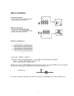
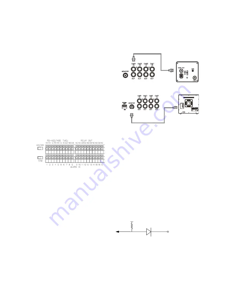
1) Camera Connection
Connect camera to the CAMERA INPUT
located at rear side of the DVR.
2) Monitor Connection
(Composite Connection Method)
Connect monitor to the MONITOR output
located at rear side of the DVR.
3) Alarm in and Relay out
Relay output : COM+NC, COM+NO
Alarm input : Short-circuit between Alarm1 ~ 16 and GND is recognized as alarm by default.
Alarm 1 ~ 16 will be corresponding to Camera 1 ~ 16.
NC = Normal Close. NO = Normal Open.
NOTICE: Sensor input is RECOGNIZED as LOW when alarm signal is on a level with GND, and it is recognized
as HIGH when alarm signal is FLOATING or 5V. Following is internal circuit.
Thus, there is a danger of damage, when the sensor input goes to a Negative level or voltage higher than 5V.
Internal Circuit
D1
5
V


