background image


7   


7   


Sub-­‐Menu:

   Shows   and   sets   the   values   of   functions.   

8   


Press   for   more   than   2   seconds   to   turn   on/off   the   tester.   Press   for   less   than   2   
seconds   to   turn   on/off   the   PTZ   controller   menu   displaying.   

9   


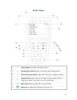
Menu   Key:

   Pops   up   the   main-­‐menu;   constant-­‐press   MODE   or   press   the   

   or   

   key   can   shift   between   functions.   

10   


Setup   Key:

   Press   SET   or   press   left   or   right   key   to   enter   sub-­‐menu   to   set   the   

function.   

11   


Up:

   Select   the   item   that   will   be   set   or   add   the   value   of   the   parameter.   Tilt   the   

PTZ   upward.   

12   


Left:

   Enter   the   sub-­‐menu   or   select   the   parameter   whose   value   will   be   changed.   

Reduce   the   value   of   the   parameter.   Pan   the   PTZ   left.   

13   


Right:

   Enter   the   sub-­‐menu   or   select   the   parameter   whose   value   will   be   

changed.   Add   the   value   of   the   parameter.   Pan   the   PTZ   right.   

14   


Down:

   Select   the   item   that   will   be   set   or   reduce   the   value   of   the   parameter.   Tilt   

the   PTZ   downward.   

15   


Confirm/Open:   

Confirm   the   setting   of   parameters;   open   the   aperture.   

16   


Return/Close:

   Return   or   cancel   while   setting   parameters   of   the   menu;   close   the   

aperture   

17   


Near   Focus:

   Focus   the   image   nearby.   

18   


Far   Focus:

   Focus   the   image   faraway.   

19   


TELE:

   Zoom   in   the   image.   

20   


WIDE:

   Zoom   out   the   image.   

21   


Digital   Multimeter   


Summary of Contents for ST-F35TESTF

Page 1: ...INSTRUCTION MANUAL ST F35TESTF CCTV Test Meter...

Page 2: ...TALLATION 9 OPERATION 10 POWER ON 10 MENU and FUNCTIONS 10 PTZ CONTROLLER 13 VIDEO SETTING 16 CABLE TESTER 17 DATA MONITOR 18 DEVICE SETTING 18 PTZ ADDRESS SCANNING 19 DIGITAL MULTIMETER 20 DC Voltage...

Page 3: ...3 DC12V 1A POWER OUTPUT 25 SPECIFICATIONS 26 MULTIMETER SPECIFICATIONS 27 SUPPORT 29...

Page 4: ...nd severely hot the ST F35TESTF should immediately be turned off and disconnected from the charger The ST F35TESTF must not be charged for more than 8 hours Do not use the ST F35TESTF where the humidi...

Page 5: ...nce can be tested as well as continuity and diode testing PTZ control Pan tilts the P T unit zooms in out of the lens adjusts the focus and aperture and sets and calls the preset position Can perform...

Page 6: ...ceived 3 Data Transmission Indicator Lights red while the data is being transmitted 4 Charge Indicator Lights red while the battery is being charged When the charging is complete the indicator turns o...

Page 7: ...ard 12 Left Enter the sub menu or select the parameter whose value will be changed Reduce the value of the parameter Pan the PTZ left 13 Right Enter the sub menu or select the parameter whose value wi...

Page 8: ...P LAN cable tester 25 RS232 Interface RS232 communication for the PTZ 26 Audio Input Test audio on the front end 27 DC12V1A Power Output output DC12V power for camera 28 ST F35TESTF Speaker 29 Video I...

Page 9: ...r off Prior to using the unit for the first time be sure the batteries are completely exhausted and then recharge for 4 or 5 hours The Charge Indicator lights red when charging the battery and will au...

Page 10: ...enerator LAN Cable Tester Data Monitors Device Setting and enter the corresponding function setting sub menu Press the SET key to set the parameters in the function sub menu Note When the ST F35TESTF...

Page 11: ...testing 3 Colorbar Generator Output or receive seven different forms of video colorbar to tester monitor cable or other equipment 4 Cable Tester Test LAN cable or telephone cable The connecting condit...

Page 12: ...evice setting Set the parameters of the ST F35TESTF Auto power off Keypad tone Language Brightness Address search 7 Address Search Search the PTZ camera s ID 8 Digital Multimeter Digital multimeter pe...

Page 13: ...amera Data A of the ST F35TESTF and A of the PTZ camera or controlling device data B of the ST F35TESTF and B of the PTZ camera or controlling device Note Do not connect the communications interface w...

Page 14: ...osition setting or press the RETURN key to escape the preset position setting H Go PS Call the preset position 0 128 The PTZ camera will go to the desired preset position a Move the yellow cursor to G...

Page 15: ...he PTZ camera or stop the PATTERN recording Call preset 96 Run pattern 1 Call preset 97 Run preset tour 1 Call preset 98 Run frame Scan Call preset 99 Run Auto scan MAIN MENU 1 DISPLAY SETUP 2 CAMERA...

Page 16: ...tically change between NTSC and PAL and the Video Level will automatically change between IRE Institute of Radio Engineers and mV NTSC signals measured in IRE units PAL signals measured in mV The Vide...

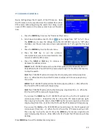
Page 17: ...and cable tester The connecting status cable type and the sequence of wires will be displayed as well as the serial number of the cable tester kit The right picture shows lines 1 7 are closed line 8...

Page 18: ...the command data from the controlling system d Press the RETURN key to clear the screen DEVICE SETTING Device Setting sets the ST F35TESTF s parameters Auto Poweroff Sets the time for auto shut down D...

Page 19: ...press any key to stop the search FAR The ST F35TESTF will search down the ID list quickly and continuously from 256 1 When the ID is found the PTZ camera will pan left Press any key to stop the searc...

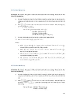
Page 20: ...ing DC Voltage Measuring WARNING An input of more than 660 VDC may show higher voltage but doing so may destroy the circuit Also pay attention not to get an electric shock when measuring high voltage...

Page 21: ...so may destroy the circuit Also pay attention not to get an electric shock when measuring high voltage a Connect the black test lead to the COM jack and the red test lead to the V jack b Press to sele...

Page 22: ...ver range situation and the higher range has to be selected When the value scale to be measured is unknown beforehand set the range selector to the highest position The maximum current of the mA jack...

Page 23: ...he operator Resistance Measuring WARNING When measuring in circuit resistance be sure the circuit under test has all power removed and that all capacitors have fully discharged a Connect the black tes...

Page 24: ...the input open circuit or the circuit resistance measured is higher than 660 then the OL figure will be displayed Diode Testing a Connect the black test lead to the COM jack and the red test lead to t...

Page 25: ...d audio cable Do not input any power to the ST F35TEST s DC12 1A OUTPUT port Doing so will destroy the unit Do not output this DC12 1A power to the ST F35TESTF s power port Doing so will destroy the u...

Page 26: ...as PELCO D P Samsung Panasonic Lilin Yaan etc Baud Rate 150 300 600 1200 2400 4800 9600 19200bps Video Signal Generation Colorbar Generation Output one channel PAL NTSC colorbar video signal for test...

Page 27: ...ergy saving technology General Working Temperature 22 F to 158 F Working Humidity 30 90 Dimension Weight 7 x 3 7 x 1 4 0 75lb MULTIMETER SPECIFICATIONS Counts 6600 6600 Conversion Rate 3 ties s Curren...

Page 28: ...1 5 10mA AC Current Range Accuracy Resolution 6 6mA 1uA 66mA 10uA 660mA 0 5 3 100uA 10A 1 5 10mA Resistance Range Accuracy Resolution 660 0 8 5 0 1 6 6K 1 66K 10 660K 100 6 6M 0 8 2 1K 66M 1 2 5 10K C...

Page 29: ...rward voltage of diode Capacitance Range Accuracy Resolution 6 6nF 0 5 20 1pF 66nF 10pF 660nF 100pF 6 6 F 1nF 66 F 3 5 8 10nF 660 F 100nF 6 6mF 1 F 66mF 5 8 10 F SUPPORT For technical support or assis...

Reviews: