X2 dp
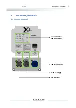
4 Connectors/Indicators
7
4.2
Connectors
XLR socket (1)
The X2 dp should be connected with a standard symmetrically wired XLR cable if the audio trans-
mission is analogue. To connect the input signal to further devices, use the male XLR Loop thru
connector. To obtain full power performance from the system, the signal source should be able to
provide a minimum of 6 dBu distortion free output voltage.
RJ45 socket (2)
This socket is used to integrate the X2 dp into an existing digital audio and control network. Digital
audio signals (AES67 standard) can optionally be processed by the X2 dp.
This function is not available in the condition as supplied to the customer and can only be used
after installing a firmware upgrade.
PowerCon blue (3)
Power supply input voltage 110-230 VAC. This connector provides the function of an on-off switch.
After powering on (turn the connector to the right until it locks), the systems starts up and is ready
for use after approximately 3 seconds. Avoid repeatedly switching the system on and off, particular-
ly when it is operating.
The nominal power consumption of the X2 dp under full power is
0.4 A (measured with pink noise, Crest Factor 8). Transient peaks
can, however, cause much higher momentary power drain. Observe
carefully the nominal power consumption when connecting the loud-
speaker(s) to the power source, and observe carefully the cut-off
current of the safety circuit breakers. We recommend using the loud-
speaker on power circuits with circuit breakers with C characteristic.


