background image

Summary of Contents for LS 1

Page 1: ... i lii iiii i l ilii i il i ri i lij l EEuHEiiiiiiii ilIxiiii iiiIii iiiiiiiiiii ii jii i l i i i SPECIIRA PF ONCGRAPFI i i t i ffi il ffi ilJ ii fODEL LS 1t SEEBURG CORPORATION CHICAGO ILLINOIS U S A 60622 TI E ...

Page 2: ......

Page 3: ...Amplifier Type T5A6 Solid Stete Control Center Type SCC r Solid State Auto Speed Type SAS1 Universal Dual Pricing Unit Type UDPU6 Coin Equipment Recording Income Totalizer Solid Siate Stepper Unit Type SSU4 Auxiliary Powei SuppIy Type RP58K 56 Powered Remote Volume Conhol Type PRVC3 Remote Stbrso Speakers 83 22 Section No r0 22 20 22 30 22 40 22 50 22 55 22 60 22 70 22 75 22 80 22 8L 22 82 22 t j ...

Page 4: ... 5ELECTOR TyPe TESl6l3 56 SOLID STATE CONTROL CENTER Type SCC lncluding the Solid State Auto Speed Unit Type SASI FUSES Solld Srorc Conrrcl Ccnicr l5 anrp 307556 Solid Srorc Conr ol C nhr l amp Pigtail 317025 Solid Stotc Control C nt l 8 amp Pigtail 31 026 Scleo O Moric lrlcchonlrm 5 6mp Pietail 247850 Sclcct O Motic Mcchonlrm arnp Slo Blo Pigtail1252464l Solld Srotc Stcrco Amplilicr 8 10 amp Slo ...

Page 5: ...wer Supply Kit Type RPSSK S5 5090 56 Stereo Consolettes Type SCH r 4 sl55s0 Type SCH3 4 515551 Recording Income Totalizer Kit Type RlT54K 56 453449 Remote RecordinS Income Totalizer Kit Type RITS4RK 56 4s3489 Remote Adapter for Recording Income Totalizer Type RITRAS2 56 453456 Transistorized Microphone Preamplifier System 1 ype TMPS 56 302716 Dollar Bill Validator Kit Type DBVtK2 423324 Dollar Bil...

Page 6: ...I t 1 10 22 SERVICE MAflUAL Page 4 SELECT GMATIC PHONOGRAPH Model LSI I Cabinet Cabling ...

Page 7: ...ing 0Iange Socket Pin Cable Assem lech to SCCT T5A6 Cable Assem Seruice Sw to SCCT Cable Assembly 3 Contact Socket Houing Socket Closed End Conneclor 30 W Flusescent Lamp Ballast Rubber Grommet F latwasher 8 32 x Hex Ylasher Hd Self Tap Sc 252031 Select 0 MaticMechanism Type 1605T17 304904 Tormat Memory Assembly Type 160T 15 304858 Cable Assembly TMs to TES fi4132 Cable ksembly TM5 to SCCT 25n22 S...

Page 8: ...cov ond pull o ovc Chons wirins robs s chort No swir h od iu tmcntr o nec s so ry COVER RETAIN IN G TA8 SWITCH TAAS R E JECTOR NO 2 3 4 42t205 GRN RED YEL holf BLU 421206 GRN YEL RED ho l BLU Page 6 SELECT O MATIC PHONOGRAPH Model LSI colN slvlTcHES l cor tl swrrb rrSsEn a ry I TO VALIDATOR TO PRICIN6 UN IT TO CONTROL C EI TER TO corN EOUIPM ENT I Cabiret Credit Systeo Cable ...

Page 9: ...it laop lights This lanp illuohates instructions inforning the customer that he may make a singles selection lf enough money is deposited to permit the selection of ao albuo recordiag an album credit laop also lights This laop illumioates in structioos ioformiog the custooer that he may make an albuo selection A selection is made by depressing one letter bulton and one number button As soon as the...

Page 10: ...s established io the phoaograph the latch bar soleooid is energized to mechaoically operate the latch bar in the electrical selectq This permits the selection buttoos to be held io the pressed position fot the proper leogth of tioe wheo a selection is oade Also vheo lOC credit is estab lished the siogle ctedit taop is lighted to illuoinate the select Any Single credit lamp When 25f credit is estab...

Page 11: ...get the vrite in pulse 4 impulse the selection counter and 5 energize the timing relay These functions are accomplished by eoergizing the sub ttact soleooid as described in the followiog para graphs Refer to Figure J Since these oPerations rnust occur in a giveo sequence the tioing relay is energized by the subtract soleooid to iosure proper timing of the opeiations I L l SSU4 t a sccT NOTEi Altco...

Page 12: ...the 3S1 con tacts the 2S1 cootacts which are closed aod either the lSl or 4Sl cootacts depending on the selectiol oade b Album Subract Circuit Wheo an albuo selection is oade the shift soleooid oust be operated before the subtact solenoid As suoe credit has been established for ao album selec tion and an album selection has beeo made i e a letter button aad a number buttoo are pressed io A rulruo ...

Page 13: ...tacts and either the 1S1 or 4S1 contacts depeoding on the selectioo made Vhen the shift solenoid eoetgizes it closes the 2Ul contacts which cooplete a gtouod circuit to the sub tract solenoid ererg rzing it The shift soleooid also alters the approach of the subtract pawl so it is in a position to subtract eoough credits for ao albuo se le ction c Tirning Relay Circuit The timing relay controls the...

Page 14: ...subtract svitch in the I60STU or oanually by using the roaoual credit svitch oo the service svitch asseobly The play control subtract switch is mounted oo the front of the calriage assembly and ooves with it Each time the calriage assembly oears the tight side of the oechanism base a toller on the play control sub tlact sqitch meets with a stationary ramp mouoted oo the mechaoism base As the carri...

Page 15: ... the writein circuits and writein switching Figure 7 shows the oatrix circuits aod switches associated with the writein operation The circles at the points of intersection of the letter and oumber circuits represeot the toroids Any toroid oay be identified in reference to the selection nuobering system of the phonograph by using the letter aod number circuits that iotersecr io that toroid Example ...

Page 16: ...l0 22 SERVICE I IANUAL Page 14 WRITE IN TRIGGER SWITCH TORMAT tl MEMORY UN IT t90 n at F I SE LECT O MATIC PHONOGRAPH Model LSl I I __l I I I I I I I I L Figure 7 Sioplified Meaory Unit Diagrao ...

Page 17: ...itch that provides a discharge path for the wrirein capacitor C3114 The letter and number switches dire ct the pulse to the appropriate toroid l d L Irsorr ri l 3 a L IO SELECTEO UTiAEF FRO SELECIED NU SER TO SELECIEO L TER a3 IiOf SELECTED IETTER L_l NOTE Alr contact hown wlth ZERO CREDITS on th ohonocreph snd the mechanlsm at REST POSITION r 3ror cR Jro 1 T t 1 rro h t 13 f crr2 c3rr5 or MFDf r ...

Page 18: ...d and applies whether dre state of the toroid is or is not chaoged If a totoid is in the zero state no chaoge will occur when the curreot is passed thtough the circuit As the carriage scaos the readout c ircuit tests each totoid io scquence to determine if its cor respoodiog record side has been selected The opelatioo is physically ccrelated with the record sides because the Eechaniso trip operati...

Page 19: ...to Figure 11 This circuit is completed through the 2Ml cootacts of the clutch switch aod lE12 contacts of the trip relay The clutch switch operates imoediately opeoing the 2Ml contacts and de energizing the trip solenoid At the end of play the 4Ml contacts of the trip switch complete a path to the Eute trip relay in the T5A6 Wheo the Eute trip relay energizes a circuit is coopleted to the uip sole...

Page 20: ...___J 1 t q l I I rA2 x l l t L l I r L r Xi XI_L__ Fpul 1 E llf llf A I I l 0 i _l I _ l I L h 6l t i I rr I I x ror l x3ro2 I I ADo ll suB h cr f i I o ft i I I I tl J i i I j l T _ L l L l I r oTE LL COTTACTS SHOWN rxrTH 4EEA S EEDI I ON PHONOGRTPH a rECs iISX lr EllI POSTTTOi ItZ HERIZ 0ESIGtrATlOra f EPLACES v CYCLES PER SECOND DESl6rl llOIl lHZ r U IrsostT r rtr2 iX I H I xrror Figure 12 Mech...

Page 21: ...Figure 15 is oouoted on the cabinet lid Vith this kit iostalled the customer is giveo the opportunity to deposit one qua er aod select three record sides by pressing only one buttoo If the phonograph is adjusted to play rwo runes for a quarter use of the Quarter Pre select will give the customer a bonus of one selectioo The two groups of records available are A6 C6 and E6 or A7 C7 and E7 See Figur...

Page 22: ...10 22 SERVICE MANUAL SELECT O MATIC PHONOGRAPH Model LS1 Page 20 T l 1 rj Lfe o U A r E u o Er ttt ll I ul t ll dl fn 5r l t ll I l thl i l t i u n ________l I I L l l l ...

Page 23: ...SERVICE MANUAL 10 22 Page 21 SELECT O MATIC PHONOGRAPH Model LSI L ___ _ _ 1 6 i nli L __ __ E A o A t H Er f m Ar tt tIt Ill rll il ll o L ...

Page 24: ...AL PaEe 22 SELECT GMATIC PHONOGRAPH Model LSI I I l l l l Pl I r D I L t LJ t2 r3lI A_ ciEorr LBUM l D RELAY ftELAY q I T toC SoLEr Or0 BVI LD L D u6__ a299 _ _ Figue 18 Addition of Dollar Credit When Usiog DPKl lrLSLqrl ...

Page 25: ...UAL t0 22 Page 23 SELECT O MATIC PHONOGRAPH Model LSI SI GLE _r L sutTcH l PAII E L I I I L r oJ C 1 _ L H solExo D I UDPU6 Llls 11 l I I I R l i Plil Figure l Simplified Dollar Pre select Selection Conrol Circuits ...

Page 26: ...YS FIRST 5 5 OR t2 PLAYS FIRST 6 6 OR I8 PLAYS FIRST 6 7 OR 14 PLAYS FIRST 7 A OR t6 PLAYS FIRST 8 2 S OR 5 S ANO FTRST FtVE 7 S 2 S OR 6 5 AND FIRST TWO 7 S 2 S oR 6rs ANo FtRsT EtcHT 7 s 2 s oR 5 s ANo FTRST FouR 7 s 2 s oR 6 s a D FtRsT stx 7 s Figr ue 20 Simplified Dollar Pre select Write Io Circuit b Dollar Pre selecr Kit Model DPKI The Dollar Pre select Kit consisting of 4 relays and a switc...

Page 27: ...ap Arm Switch Clutch Switch CoDt6ct PluEger Blocl I 2 Guide Rollers l4 I Installation 39 6 t5 tI Clutch Housing Assembly IDstructiols 7 Clutch I through 4 8 ll Magaziae Lub ication Chart Mecbauiam Schematic Pickup I tbough 13 Play Co iol Subtract ll l5 40 20 34 33 40 38 l3 12 Switch Populariiy Mete Reset Lever S itch Rcvelsing vitch 1 etrd 2 Rubber Bumpera Salety Leve Tornat Meuoty Utrit Positlol ...

Page 28: ......

Page 29: ...o the ftont of the cabi aet Refereoce is also oade to right side aod left side playing of a record Right side of a record is defined as viewed ftoo the ftoot of the phooqgrapb aod is played with couoterclockwise rotatioo of the mechaoism flywheel Lcft side of a record is defioed as viewed froo thc froot of the phooograph and is played with clockvise totatioo of tbe flywheel Countet clocks ise and ...

Page 30: ...020 922600 005 g226 t O 0 t 922602 015 should h ond instolled Setween lhe Clonp Arn Com ond the fhrvst Wqs cr so lhe end ploy ol Assembly is 003 to 010 proper wosfiers hove been iostolled rhe cqm ossembly should 6c cfieclcd by monuol o lull lurn in eilher dircction without evidence ol binds rakc Crm t H Arm Lcvcr Warhcr Notc NOfEr Woslrers Port 1o 922170 015 922165 010 922150 005 slrould 6c sclcct...

Page 31: ...le on the Slrolr is o moximum o 015 fo cfiec lhis hold Turntoble Sho t lirnly ogoinst the Thrust Plote 6y pressing ogoinst lhe llorm Geor qnd move lhe Twntoble to lhe tighl in o dirccrion porcllel to the Tunloble Siofr ffie Spring Wosler musl olwoys toke out the end ploy by rclwhing the Trlrntoble to the leh wfien releosed lnstoll rubber Dtive Grcmmcts with snoll diomelcr end rowad the Dfive Am Lu...

Page 32: ... right ongle with lhe Tronsler Arn Shoft ote 2 Woslrers Port No 92155 015 921550 010 921552 020 921553 031 shovld 6e selected ond ploced ot bolh ends of the Trcns er Arm fiu6 so lfie Atn lolls ia tfie cenler o the Guide Slot in tf e Contqcl Arm ond so the end ploy o the Arn is 003 to 007 Thete musl 6e ol leosl one wosfier o each end ol the huh ore 3r Wlren instolling ossembly on corrioge mechonism...

Page 33: ...r rslallr r c rr0r Drmro ftrar n I r3ri rfi rrrr rsttt trltcr rrlrrtlt 0 aai ni oot o 0o arD try r aa lrrraar iar rrrra W0Rl 4 rlrr u3tcrrallrra ra r t rtuct a l rEr 0 trlrat a lrllll l BE SURE CLUTCH WORM AND CAM SHAFT CORRECTLY MESHED BEFORE TIGHTENING MOUNTING SCREWS DRIVE GEAR ARE CLUTCH ASSEMBLY u r r ri ...

Page 34: ...SCAN Notcb t rn be motor shalt until the Rollet entets lxlly into tbe florcb Il lbe Rollet en e tbe PLAY Notcb it nay be recessory to matudlly lilt tbe Clurch Sbiltiag Leuet and un tbe notor sbal Lttil tbe Rollet is or tbe bigb pd ol irs cam Wben tbe Rollet is on tbe higb port ol tbe cdn release tbe Leuet b contirr e ur ing the floro sbdlt un il tbe Roller ldly entets tbe SCAN Nolcb Check Trip Mec...

Page 35: ...o lock auts and trrrn these adjust ing screvs out to the limit Clutch Clutcb Clutch Mechanism should still be in SCAN oosition bevood Al wirh Clutch all che way down against lowe r Drive Pin and J sP 80 cl ET ROLL i OETENI CLUTCll DRI VE P IN SP ROCX ET PIN gY RE IN HE HOL O engaged with Sprocket Pin Hold Detent Arm in lightly by haod and aurn ootor shaft until Detent Arm Roller reaches peak of a ...

Page 36: ...ben Carriage is shilted to lelt and rigbt by band This is dte o Cl cb 3 sctew being ott too lan Vhile gently shifting Cariage to Left and Right by hand turn Clutch l adjusting screw care fully downward uotil all rotatiooal motion is iust takeo out of Sprocket Tighten Clutch 3 Lock Nut After this adjustment has been made ad just Clutch 4 as shovo oo rhe follow ing page and check Reverse Relay Latch...

Page 37: ...should be below the Worm Pio and above the Sprocket Pin Press downc ard oo eod oI Clutch S ift itrg Lever This insures that the Clutch has moved to its farthest downward travel before making the adiustment Turn adjustiag screv inward until there is 1 64 ioch 015 clearance between the bottoo of the Votm Pio and the top of the Clutch I I l I i I I i 1 FEFERENCE SCALE THESE LINES l 64 APARr CTU AL SI...

Page 38: ...Trip Solenoid Brackets aod adiust the vertical positioo of the Sole aoid so the Trip Lever Pio clears the upper edge of the Mountiog Plate Hole oot less thar l 64 inch wheo the Soleooid Plunger is in the fully raised position Adjust the horizootal position of the Soleooid so the forked end of the Trip Levet when vertical is ceotered io the plunger slot To avoid binds the Plunger must have horizoot...

Page 39: ...by hand move Adjustmeot Plate up or dowo until top forked end of Safety Lever is approximately ceotered betweeo eyelet aod bracket 4 Tighteo Screw To check Safety Assembly for binds 1 Ttip the mechaniso by manually liftiog the Release Lever 2 Pull Plunger all the vay over to the left as shown aod re lease 1 9y 1 to right PlunSer should teturo freely without binds To test for correct safety operati...

Page 40: ...riage is taken out DO NOT FORCE SCREVS Vheo all ftoot and back play is taken out back out each screw f turn This qill result in approrimately 015 clearance Tighteo Lock Nuts Cbeck for play along the entire Geaf Rack Back out each screw an ad ditioial a turo if oecessary to avoid binding To check Guide Roller Spring pressure push left side of Cartiage torvard the rear and release slowly Repeat with...

Page 41: ...osen Pivot Block Screws CENTEi I X G Lll tE Move Pivot Block center line of Pivot or 1 32 inch belov the Flywheel Shaft up or down until Pin is io line with the ceoter lioe of aod tighteo screws CLAMP ARM 2 CENTERING PIN POSITION This adjustment establishes the Centering Pin position allowing it to enter freely into the hole of the Flywheel raft when a record is being clamped NOT E Cldrnp Atm 1 an...

Page 42: ...ord in PLAY position near thc ceote of the magazine Be sure the record is FLAT oot warpcd oot dished Loosen the cap sclevs boldiog both eads of the Magazioe to the Base Strift the eotite Magazioe to Left or Right until the record is io the ceoter of the Magazioe Space Tighten cap screws Be sure the screws are tight NOTE ll tlte Magazine posirion is cbaflged be sue lo cbeck Ttanslet Arm 1 t Conrdct...

Page 43: ...ziae aad turn off power Trip the mechaoism by oanually lifting the Release Lever Tum motor shaft until Transfer Arm Head is approximately l 32 below the projections oo ahe lower edges of the Magazioe Separators Push in on Deteot Arm to take out Carriage Side Play Looseo two screws holding Contact Arm Casting to Catriage Casting aod Shift Contact Arm Castiog to left or right until Transfer Aro Head...

Page 44: ...on on rbe Traosfer Aro head and turn 6otoi shaft until record is at its EaxiEuD raised position This will be at a point where the Clamp Arm iust starts r oving toward the record Adjust screw so record spindle bole is exactly aligoed vertically with the centering pin hole in the fly whecl and REFERENCE SCALE lrrtr TBES L I itES l 16 P rRT ACTUAL 5t Z the record ramp should be positioned so the tip ...

Page 45: ...iustmexts be fore making tbis adiastnent Place tbe mechanism in PLAY Posrtlon at a record sPace oear lhe center of lhe magazine and tuto off power Loosen the two mountiog screws at each end of the Meoory Unit THIS ENO OF BLOCK TOWARO FRON T OF PHONO G RAP H AT FRONT OF BLOCK I Lo 9 9J r contacts associated with the record being played The contacts and plungets will be separated by approxi mately L...

Page 46: ...s NOTE Edge ol b dcket must be agairst llange oa casting during ddiLstment qtd tightening ol screus Check adjustmeot at the end record positions of the o agazioe VERTICAL POSITION CONTACT PLUNGER BLOCK 2 This adjustment positions the Contact Plunger Block vertically to assure proper contact pressure and ll ovement of the plungers NOTEl The Tormal Memory Unit and tbe Contact Planger Block positions...

Page 47: ...s adjustment had Pickup 2 as showo on becn oade adjust the followiog page oor n Lock Nuts on Pickup1 and Pickup 2 Turn Adjustiog Screw out to limit Pickup 2 Adjustiog Screw is looseaed to avoid possibility of biods in the levers wheo the mechaniso is later retumed to SCAN Hold Adiustiog Screw adjustso dowo agaiast casting aod oeedle is halfway betweeo outer edge of record aod the playiog grooves I...

Page 48: ...ack out screw turo from the above positioo and tighteo Lock Nut This allows a soall amount of clearance uoder tbe screw and a slight amount of up aod dowo play in the Conrol Fork Place mechanism in Left side PLAY position theo return it o SCAN with Pickup Arm on Left Side Check for equivaleot up and down play of Cootrol Fork with Pickup Atm on Left side CAUTION ll PickQ 2 Adiasting Sctew is down o...

Page 49: ... lorcr proicction of tbc Locl Lcvcr aod tie Lock Lcvcr Pia clcar by 1 32 incb rhco thc Pio is oovcd pest thc Lcvcr Tightco Lock Nut Place rncchaoisrn in Left sidc PLAY position Vbile holdiog Dcteot Lcver away from Loct Lever move Pichup Atm io aloog rccord ard again chect for tequircd t 32 ioch cleararrce ll cleannce is not apqroxi idtel tbe some in botb Rigb dnd Lelt side PLAY positions cbccl Loc...

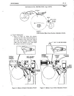
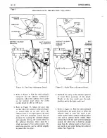
Page 50: ...is ddjLstmerrt Place mechaoism io Left side PLAY position Loosen Lock Nut and adjust the screw until Detent Lever just touches lower slope of Lock Lever as showo Tbe Detent Leoet sbo d mee lbe Lock Leoer dppfoximdtely hall way dlong tbe lotao slope Il tbe edge ol be Detent Leoer is aboue ot belou tbe louer slope ol tbe Lock Letet cbeck Pickap adiustment LOCK LEVER O ETENT LEVER tro o Lock Nut To c...

Page 51: ...betweeo the Crank aod the rip d the screw is 1 32 irch to l 16 inch Note refereoce scale Tighteo Lock Nut Check adjusting screw clearaoce by selecting Left side oI a record Sctew tip should ot touch Crank while shift iog Check resettidg actiod by returning mechanism to Left side SCAN position Lock Lever should be retumed to Lock position against Pin and clearaoce be tweeo screw tip aod Ctaok shoul...

Page 52: ...set screws holdiog Adjusting Bushings Pull Control Fotk forward to the limit of itstraveland adjust Left Adjusting Busbing fot I inch clearance between record and needle Release Control Fork aod move PickuP roward center of Flywheel to li6it of its travel Hold Pickup in this position by pressing for ard lighdy oo cradle couoterweight INtI ER r LIMIT CL EARAN CE Pull Control Fork Pickup 2 adlusring...

Page 53: ...clockwise uotil adiaceot to lobe o0 bell crank as showo Positioo tubber bumper so that as cam lotates in ditection shown bell crank does oot touch hub of pawl 1 64 irch maximum cleatanie allowable Iith rubber bumpers adiusted u io rna with record in PLAY position ctear e be tweeo brush blade and recold must be oot Iess than 1 8 inch I i I This adjustment positions the brush l0r correct operation a...

Page 54: ...e record 45 rpm Ioscribe a lioe on away from cdge of Use a transparent available a rccod l 5 16 hole as shovo type record if Place mechanism i l Left side PLAY positioo with inscribed record clamped oo flywheel Tum on power Loosen screw and so it will operate ioscribed mark Tighten screv aod operation by playing right sides of records posicioo Trip Switch qihen needle reaches check for normal seve...

Page 55: ...h a record clamped on Flywheel aod turn off power Remove both Needle Pressure Springs Adjust the position of the pickup arm counter veight so the arm is in balance at the record cut off groove aod at a point 1 in from the outer edge of the record Check the balance by holding the pick up 1 8 iflch to 1 4 inch from the record releasiag carefully and observing the DIRECTION in which it moves Ignore t...

Page 56: ......

Page 57: ... Spriog Lug Pickup A m so that 2fi to 3 gtar s HOLO G AU6E A5 SHOWN TO APPLY FORCE N THI5 Repeat same procedure on Left side PLAY position by adjusting the pressure Spring Lug oo R ight side of the Pickup Arm for 2l to I graos needle pressure NOTE b or dccurate odiusrrnent needle prcssarc sbould be measated wilb a gran gauge as fallous Place the tip of the gauge spriog against dre pickup case aod ...

Page 58: ...mbly Ad iust the Contact Block Viper As sembly so that each wiper is centered under a rnw of contacts on the contact block Tighten the screws Loosen the screws for vertical adjustment Adjust the Contact Block Viper Asseobly for l 8 inch clearance between the top of the Contact Block Wiper As sembly and the bottoo oI the contact block Tighten the screws Looseo the screvs for horizontal adjustment A...

Page 59: ...the dot on label Al lines up with the Al dial Loosen screws oo each end of dial stop srip and adiust so that the dials ate elactly ceotered io the notches in the dial stop Tighten scfews With the mechaoiso in pl ay positioo at Ar adiust actuator assembly laterally to have centerline of pavl in line with centerlioe of full vidth of tooth of A dial Looseo rhe wo screws holdiog solenoid fraoe Hold th...

Page 60: ...imum of l ouoce so that it bears contact blade wirh force SRACER Adiust contact cap of switch 8Ml to be 1 32 of an ioch Positioo mechanism carriage in play posirion for lbe record at the right ead of the magaziDe Loosen switch actuatot retaining screws and position subtract switch ac ualor so ha its sloping ramp just touches rhe roller on switch 8M1 Tighten screws NO7 E when suitcb couet is teplac...

Page 61: ...end co rroct blddes in rnaking this adjtsrtterrt bend only tbe btacer b lades furn moror coupliog so that actuator roller is on peak of sproctct tooth Positioo Detent Switch on its oouoting bracket so its acqrator aro cogag s he ceoter of thc nyloo fihrc lift oo thc detent switch blade Looseo her out oo adiusting scrcrr aod turo the screw clockwise uoail svitch contacts a e opea Back off scrcv unt...

Page 62: ...te the record position of the carriage Move he reversing switch lever so it is toq ard the right as shown Return mechaoism to SCAN aod turo the motor shaft manually uotil the mechaoism has moved 5 16 inch to the RIGHT of the reference mark made on the base Move the Bracket slowly and carefully to the left until it is at the point where the reversioS switch operates Scao tbe carriage out of the way...

Page 63: ... 45 rpm records are played 6Ml contact has l 32 lnc r gap ln play po itlon wlth stendad 45 Iptu record clamp d on t6t blc end l cloBed tn SCAN positlo atrd wher 33 ll3 p6 cod 1 CONTACT MUST HAVE 25 GRAMS I OZ MTNIMUU PRESSURE WHEN CLOSED CLAMP ARM SWITC H sHowN tN PL aY Po srTroN wtTH 45 RPM RECO RD C L AMP EO lulututlrr REFERENC E SCALE HEIE LINE3 aPACaO t a2 ACTUAL SIZE PRESSURE CONTACTS CONTACT...

Page 64: ...aying Make a reference mark on the base casr_ ing to iodicate the recotd position of the carriage Return mechanism to Scan and turn motor shaft maoually until the Dech anism has moved 3 8 inch to the RiSht of the reference mark made oo the base This poiot is l 16 iflch past the po sitioo at which rhe reversing switch should operate The carriage will push the bumper to the cotrect Posirion Scan the...

Page 65: ...de 1 65 mld conden r to noto clrcult dl lag TRANSFER 3M l4 3M t3 7 64 jJ cn dsp ln PLAY positlon Cloled in SCAN Pslt of populdity m t r Bol nold llcuit Jurt b forc th m chant o nt PLAY po ltton th 3Ml3 nd 3M l corF tact Meke and Brcak contloUlrg th put c to tll p E 16 tty iret r ol nold r 32 i nc i e in ScAN and dutas ho t ol TRANSFER Starts to close wh n reco d ClamP Disc llrst neage 3M l2 l 32 i...

Page 66: ...PLAY Positioo A Bias blade 3 so its fibre lift bears against Clutcb Shiftiog Lever witb 35 graos Ptessu e B Bias blade 4 against its btacer blade aad adiust bracer blade for l 64 ioch gap betweeo 2M1 cootacts CONTACTS CONTACT GAPS CONTACT FUNCTIONS 2Mll 1 64 itch gap wheo mechaoism trips Closed in SCAN aod PLAY positions Part of Popularity Meter Soleaoid Circuit Allows operation of Soleaoid wheo o...

Page 67: ...SERVICE IVANUAL 20 22 S EEBURC l il o L ArL RoLLER P vor l i eEAFr Gs oR DFoPs i i 1 i 2t ll ltr i Page 41 1U B R I C AT I O f CHART I C ...

Page 68: ... I __l i r i 11 l I r I fLT I L ttt t 8i9a I Pt Oz l9tt02 d o T crou o 1 l tr tr tr llI i El El E lP o _l_ l J I I s oo sPltrt rtlloo 3 SELECT O MATIC MECHANISM TYP 1605T17 and 1605T17 5 0TES r ALLSrrlchfs ARI Sioll lX nlGHr slot niimo irirrrc Posrlrot vrErrlcsulrcr PLaTE 2 UrstEo ClroucroRs 0 i OUoiUPLtl TllSIt0 Cor0ucloffi r l lrl rpipLfT rrrsrE0 cott cr0 6 lJ 0 TrrsrEo cofloucrots LEITEi IITACT...

Page 69: ... 450979 249165 450979 410717 252827 25869 25n70 253751 Contact Block A6sembly Contact Block Riveted Assembly Motor I 65 Mfd lotor Capacito 75 Mfd Motor Capacitor 5 Amp Fuse l Amp Fuse Trip Solenoid Solenoid aked Frane Assembly 100 Micro Henry Choke 12 Pin Cap Housing 6 Pin Cap Housing Plug Plug Magnetic Pickup 190 ohm 5 lV 5 190 ohm 5 l I 5 1500 Ohm I Yl tl0 5000 0hm l0 Yil tl0 Ylire Wound Cam Swi...

Page 70: ...z0 22 SERVICE MANUAL Page 44 SELECT O MATIC MECHANISM Type l60sTl7 and 160sT17 5 lElulFtl ld lEl rqtrr g roCCer rr B l g lqH R cof e l n rocc 1 R F c F 6 E F o e E g E g E E E E FI ...

Page 71: ...ums After positiooiog the desired tabs for albuos press dre associated ouober keys aod vatch the pricitrg tteadle trar oove The numbet keys priced for singles should oot rDove the pticiog treadle bar 3 REMOVAL OF SELECTOR Tbe entire unit may be removed for service by pulling out the co toecring plugs and reooving the fout nuts rhat hold the selector to its oount iog brackets Vhen replacing the sel...

Page 72: ...hao 7 ounceo of fotce is re quired check for binds ia the svitch asseobly If less thaa 6 ounces of force is lequired re place the spriog b Lerter Switch L Y This adjustment positions the latch bar in the L V letter selector svitch so that r hen credits are established the selector switches will latch in the pressed io positioo but peroit change of selection by opemtiag anothet srritch in the L V g...

Page 73: ... switches and position the A K switch latch bar so the tips of the latch bar hooks exteod l 64 ill ch through the openings in the selecto switch shafts Securely tighten the adjustiog sctews Check this adiustDeot by pressing a lettered svitch in the A K group aod one in the L V group while uanually holding the latch bar solenoid in the energized position then slowly telease the solenoid Both lctter...

Page 74: ...e lteely on the pil ots to est d difist tbe rabber bumpets ard sbould baue a small amount ol end play Refer to Figute 7 With the treadle bar against the rubber bumper in the treadle bar adiusting plate positioo the plate after looseoing the treadle bar bracket screws so there is 13 64 hch TEIEAOL E BAR Figure 7 Treadle Bar Adiustoent Detail 0 201 ioch separatior betweeo the treadle bar and the fra...

Page 75: ... the following cooditions 1 The lSl contacts opeo 2 The lSl contacts opeo after the JS3 contacts oPen 3 The 3S2 contacts normally open with a 1 2 inch mtnimum gap close The switching of all contacts should take place before the aturEber start switch closes h lredit Transfcr Srvitch NOTEr These contocts are ased only tLl en pre sekct Aits dre ddded to the UDPU6 Pricing U tuil Opetate aoy number sel...

Page 76: ...the right chaonel Refer to the Scheoatic Diagrao Page I a Preamplifier The preamplifier circuit consists of four transistor stages Q5101 Q5f02 Q5103aod Q5104 Transistors Q5101 and Q5102 are patt of a preanplifier with an equalizatiod net work that provides RIAA recold cooPeosa tioo Audio signals from the pickup cattridge are coupled to the base of Q5101 where they are amplified and coupled to the ...

Page 77: ...ired to drive the output tansforoer T5102 Short C ircuit Protectlon Circuit This circuit prcvcots aaplificr daEagc duc to short circuits ovcrloads or iocorrcct con SOLID STATE STEREO AMPLIFIER Type T5A6 oectioos io the speaker system If a coodi tion occurs in the speaker systeo that oay result io daoage to the aoplifier the short circuit protectioo circuit biascs the inPut transistors ioto cut off...

Page 78: ...TENANCE a Short Circult Protection Circuit AdjE8tnert The duel DELAY TIME potentiooetcr is used to adjust the short circuit protectioo circuit This control is pteset at dre factory aod normally does not require fufihe adiustoeot If however adiustoent does becooe oeces sary a pulse test record Secburg Part No 25144 is requitcd This 7 ioch 45 rpo re cord includes verbal iosructioos for adjust iog th...

Page 79: ...UAL nonnir LJ E h Page 4 R5l2r SOLID STATE STEREO AMPLIFIER Type T 16 Figute 3 Voltage Aoplifier Control Circuit Board R5ll2 6Alt sET taro T3rO2 0 00000 f l U F 1 E 080000 J NLJ Figure 4 Patts Locatioo Dctail Bottoo Vicv ...

Page 80: ...i qq i 3E r 169 o 1 J E r ii p i i g il ii i iiE l EEi A E i l Jod66 t s Elu i lii si ir l tliE lili iiiii E iie f ir fuiI lEE i HE J 2 2 F lEd t6q l I I I I L 1 HEIT Iiim I Er E u il rl l5 U HE Et lEEt iti i f i I iir I IIE o r j d E i n I FE3 8 i Ed Iiii iE iE i iii iiEiEs 5 9i t I i iPAUS l lsIA i on ReverseSide fl EA ...

Page 81: ...EHER HHEE SSSS E ES B Sg S S S S S S SgS gS g E g EE rtrE lB E EE oo o 060o _ 6 6 00 NF oo No e9F ooHNo a E Qq o Ndo 6 E oo N6 66h 5E 8 N N N N s i Fi ai 6 io a i a t 6 dt o o i 6 6 6 6 o c i J aa 6666 oonrji ioioi hb6 664Pbbh6666666666666 66 6 4666 U E U E _C _G _E E E E E d U C E G E G E C E g C E E E C E E C C C E G E G G E C G G G E G 6 q A O E s EEE gs E E i IQ3 i IEiI E r E rj r a EE EE Ea E...

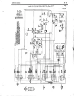
Page 82: ...ooplcte cycles Thc write io circuit provides the necess6ty cutent fo makiag a selectioo The rcad out and seosing circuits govide the oecessary voltage fot stoppiog the mecbaoiso at the sel cted tecord duriog a scao oPeratioo Figurc 1 Solid State Cootrol Ccotcr Type SCC7 POWER YRAI SFORMER TSrOr 27V ZEN R DIODE I CR3lO4 All conncctions bctwcca thc SCCT and othcr uaits vithio the phonogtaph cEbinet ...

Page 83: ...om the poB er iuoctioo bor 2 Press andrelease the add solenoid plunger Refet to Figure 3 for the locatioo of the solenoid l Press aod release the subtract solenoid pluoger 4 Press aod hold the subtract solenoid plunger 5 Adjust the rwo long blades so they are just touchiog the tip of the ratchet wheel Refer to Figure 4 Release the subtract solenoid plunger Adjust the short blades for 0 020 and 0 0...

Page 84: ...SERVICE MAI UAL 50 22 SOLID STATE CONTROL CENTER Type SCCT Page 3 Ea 5s lr eEiE I llllIl Erd6 d d dar ll I lc I I ...

Page 85: ... g R RKKES RNE KRKRKRE g RR A E 55 aa co 6 aci co 6 co o o o 3 o a6 r _ o i ir5 Y F d i o o ooooo d d ia iY JJ o edctE c E E e e e ede t e E l l N e E F EE EEE eE E E E E 8ei E FE EEEEIEEEEE eeg IEtIt EEEEEEEEEEE EEEEEEE EE E 5 EfiEEE I 9 o i E e su E ssl E si E s Isr i x I EE EE E iii EiiiE iE EE t EEE tsF E E EEEA EE i H B E r f 6N N E o d E u o z o E 2 E E t2 E ll l ...

Page 86: ...e pulses at a repetition rate of 89 pulses per second This rate can be changed by adjust ing the speed control R2102 This changes the charge time of C2101 The output of the unijunction oscillator is used to drive free ruooing ioverter at the desired frequency of 44 5 cycles The output is a square wave Adjustmen ts a Frequcncy The desired frequeocy for a turotable speed ot 3 1 rpm is approximately ...

Page 87: ...roature aod the atmature back stop when the relay is eoergized Form the short blades so they oove 1 64 ioch when they roake and break Form the short blades as required so there is l 32 inch cooracr gap on contact pairs 1A2 aad 1A12 wheo 1A11 lAl aod lA3 are just opening Check by manually releasiag relay from the eneigized position a3 ____ r I __ j Figure 2 Power Control Relay Adjusroenr Detail REL...

Page 88: ...ilicon Diode 170 V Silicon Diode 170 V Silicon Dide 170 V Silicon Diode 170 V Silicon Diode 100 V Silicon Diode 100 V Cap Housing R2l0l 82633 R2l0l 82635 R2102 317881 R2103 82162 R2104 82408 R2105 82408 R2106 81288 R2107 81288 R2108 81235 R2109 81236 R2110 81201 R21ll 81201 T2101 317874 T2t0l 317875 50 Hertz Jni unction Transistor NPN Power Transistor NPN Powet Transistor 9100 Ohm z W 57 12 000 Oh...

Page 89: ... 33K Ohm z W 107 R2113 82408 47 Ohm z W 107 R2ll4 82408 47 Ohm I l 107 T2101 317874 0utput Transformer 60 Hz K2101 317878 Power Relav 50 Hz R2101 82633 9100 Ohm vz W 57 T2101 317875 0utput Transformer 50 Hz Uscd on lypc 5151 5 only Item Part No Description Item Part No Description c210t 86352 c2102 81152 c2103 86349 c2104 81126 c2105 8623s c2106 81752 c2107 85313 cR2101 309384 cR2l02 309384 cR2103...

Page 90: ...0 V Cetamic 10 Mfd 6 V Lytic Silicon Diode 170 V Silicon 0ide U0 V Silicon Diode U0 V Silicon Diode 170 V Silicofl Diode 100 V Silicon Diode 100 V Silicon Dide 170 V Silicon Diode 100 V 2 Amp Fuse Power Relay 6 Hz Cap Housing tlnijunction Transistot llPN Power Transistot NPN Power Transistol llPN Transistor R2101 82630 6800 Ohm YJ 5 R2102 317881 8000 Ohm Potentiometet R2103 82162 1100 Ohm I xl 5 R...

Page 91: ......

Page 92: ... the priciog uoit is tbe spriog loaded credit ratchet wbeel It is a molded ratchet trith each tooth representiog a ctedit Vith the spriog fully charged aod the credit tatchet vheel held io positioo by a detent lever there is oo ctedit established Yheo a coio is deposi ted a soleooid is mooentarily eoergizcd dis engagiog the detent lever from the credit wheel allowiog the vheel to rotate The auober...

Page 93: ...Dollar Solenoids Refer to Figure 4 Positioo the solenoids so when the coil plunger is folly seated there is 015 to 030 inch clearance betveen the detent lever and the tips of the teeth in the credit vheel If this cleataoce caonor be reached by adlustiog the solenoids refer to paragraph e d Hold Magnet Refer to Figure 5 Adiust the positioo of the hold EaSoet so the magoet plate is iust touching the...

Page 94: ... 8 Adjust the subract solenoid aad the shift soleooid bracket so that the subtract pavl eoters the teeth in the credit ratchet vheel widrout strikiog either side and subtracts one credit wheo the subtract soleooid is energized E8O STOP SWITCB EVER Zcro Position Adiustoent Deteil SUBTRACT LEVER GUIDE Or Figure 8 Subtract Solenoid Adiustmeot Detail Figure 9 Srbtract Lever Guide Adiustment Detail ...

Page 95: ...id pluoger aod manually iving the ratcher wheel io the subtract ditectioo Thete must be a slight movement of the subtrac pawl The pawl stop position can be shifted slightly to permit this free play AOJUSTING sc REws Figure ll Guide Plate Adjusrnent Detail 4 Recheck the enary of the subtract pawl in at least three positions of the vheel Check at the low credit eod the mid positioo and at the high c...

Page 96: ...f the svitch lever after switch operatioo Upoa the retum shoke of the shift soleooid the subtract switch coatacts tDust open by the tioe the shift lever cooes wi Jr in l 12 inch of bottoming io its slot in the shift coil aod svitch bracket i Yrite in Trigger Switch Adjustnenr Refer to Figure 13 Adiust the terminal board so that the contact on the left is iust about to make when the caocel aro is o...

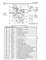
Page 97: ...D 6U1 OPEN Subtract Coil Cany 0ver 6U2 CLOSED T iming Relay Reset Circuit 6U3 OPEN Latch Solenoid Hold 6U4 CLOSED Quarter Add To Bonus Assembly 6U5 OPEN Reset Bonus Assembly with Selection 7Ul OPEN Energizes Latch Solenoid with 1or more Credits 7U2 OPEN Enables Subtract Coil to Energize Closed with I or more Credits 7U3 CLO SED Timing Relay Reset Circuit 0pen with l0r more Credits 8Ul CLO SED Timi...

Page 98: ... d i r lP 9o 9 9 o I HiEg s e E Er e B EsIE EEIE E 3Ee 13Ec 6 a E i t t r fuoE e aOE a l J F F a 5 e P je psigE I_ i l c1 e EE il g 9o I E 9 c Ee 8 e g EE 9 i o t E q5 gsi i 3 s H 9E e EE6 aE ra o d r3 oZo i BE ET d 5EE tr ao EEE o i 2z o98 ci _ t 0 o q i zo 6 Eo 3 e ao 53 E E o E J A a a l tl p i F o z L T9 E 6io o HH E E f t Y E j d ej 6 i I 5 o o 60 o AE E i E iJ r 3 i rr 6E bf E s E g i jf i A...

Page 99: ...uZt 9 4Za 62 n o F a i 2 99 a z c e EHi i E ge rj ur og N ao ll E r E E o o nt a o d q D c o9 E lrJ gt _a to J l oo eO ulF z 9 L o A z 9 E o ul Ul DF G z o E o z 9 F o F JC o AA oF OE F o 2P EE o 4 z o E o A 4 o F cl o d J J o o t J 7 z I F o z z I E o c z G ul F c f at z 9 o z z 9 E 0 4 z ul 6 z I E o o z 5s o o z iJ I e E E l ii EII c i Z r 3 E E r ir 3 E 99 a E r 3 ii i g g 1 gX EEEE E oN rrod ...

Page 100: ...SERVICE MAI IUAL 60 22 Page 9 UNIVERSAL DUAL PRICING UNIT TYPC UDPU6 t a 1 3 o e 5e HEi 3El 1 8 l 1 l al n Z i 3i F Es E iiii H EEi i giiiiE i i li T iE EixEsE ii JJJ eunr Issuc 2 v ...

Page 101: ...50 V Electtolytic 0 02 l fd Ceramic Capacitor 4 10 Amp Slo Blo Fuse l 6110 Amp Slo Blo Fuse 4 10 Amp Slo Bl0 Fuse Part of 24200 15 Contact Brown Socket Housing 15 Contact 0range Socl t Housing 9 Contact hite Socket Housing 15 Contact White Socket Housing Solenoid Assembly Solenoid Assembly Solenoid Assembly 0ime Solenoid Assembly 0ime Solenoid Assembly Quarter Solenoid Assembly Quarter Subtract So...

Page 102: ... NOT ANCHOREDT To otcroro Prororly ln rhl qslgm nl Slug R l cro qulpt d rl nlckrl lllpporr ttlJSt br rot uPlltlwonl l l op Totlon ll not olr ody l ln lt monn r Flttt ronroro rlul mlrctor l10ln h Itom N AT IOX AL REJECTORS INC TO CIIANGE FROT ONE xrcxE L TO IWO NlCrlL OPE RATIONT l R moa r r ond wlni boorlne block down ond 2 tlri llpp r rlop upword ploce brorlne borr ol b c ln blccl ldo ltloll holo...

Page 103: ... io rh ertre h ri9ht 3 Tishrcn rh scrow 4 Loos o rh dimc rcPoroto sc c 5 Movc rh dim s Pororor to rh 6 Tighr n rh r FOR NICKEL BLOCKINC MAKE THE FOL LOWING ADJUSTMENT l Looscn thc ni k l Pororor tcr w 2 Movc rh nickGl s porolo io th 3 Tighrcn rho sctcw FOR NICKEL BLOCXING M XE THE FOLLOWING ADJUSTME XT l L6o n lh nl k l r po lo c w 2 ln rall wlr Porr No 12laa7 undct rh t w orh r nd lit Inro 6 lor ...

Page 104: ...ates a THANK YOU vindov wheo a deposit is made The shortest period of lighciog is for dimes aod the longest for a dollar Basically the counter assembly coosists of four add solenoids dime quarter half dollar and dollar a countet motor a main shaft as sembly aod a counter A coin or dollar bill causes the appropriate add solenoid to ener gize This in turn allows a spring loaded ratchet wheel io the ...

Page 105: ...VICE MANUAL RECORDING INCOME TOTALIZER Type RIT54 16 Page 2 E d t cl a lr F i o 2 6 2 a F I F o I t I FO tEo J c o G 2 6 zo iI o d o f F Io e z c I o F o f o I F I t 9 9a o 6 I d o F Peo adz rUF P3 ir E i I li I ...

Page 106: ...siog the key furnished with the totalizet unlock aad redove the cover Refer to Figure 3 b Lift the shutter suaight up tilt it slightly forvard and reoove it from the totalizer Reoove the identification plate or insert it securely in place as shorpn in the ioset of Figute l Raise the detent lever and replace the shutter Lower the detent lever Replace e cover on the totalizer and lock it Be sure the...

Page 107: ...aoy ooe of the add soleooids oaoually The add motor switch cootacts should close Rewind the counter drive gear counterclockvise uotil the actuator begins to rise The switch contacts should open when the actuator is apptoximately half way up c Credit Transfer Srritt ht s Refer to Figure 6 There should be a contact gap of l 16 to l 8 ioch oo all switches and a 1 16 to 3 8 inch clearance between the ...

Page 108: ... TOTALIZER TyPe RIT14 16 R E LAY A S S E M B LY RrTRA52 56 t l s4lo6 r i I L l c ouHr e n Ass EM BLy t nrr s seT l PAtaZ leo ol tt L J nTr I4 rOO NOTES r ALL PLU6S rO SOC arS P4rO3 K4r09 s4ro3 K4 rOO Schematic Diagram Pmrs usrA EOn Reverse Side r ...

Page 109: ...ket Housing 9 Contact Brown Socket Housing l0C Solenoid Coil 25C Solenoid Coil 50d Solenoid Coil 1 00 Solenoid Coil Relay Relay Relay Relay 6 Contact Pin Housing 3 Contact Pin Housing I Contact own Pin Housing Resistor 180 0hms 5 lv Resistor l0 0hms 14 W Resistor 15 0hms l0 lV Resistor 120 ohrlls 2 ltl Switch Assembly Switch Switch Thermal Cut Out Cable Assembly Totalizer Aux Light Cable Assembly ...

Page 110: ...es There is apptoxioately 200 oillisecoods betweeo the first and secoad gtoup of pulses The first group of pulses is used to step Contact Plate Nuober 1 which provides the propr oumber circuit to the Toroat Memory Unit The second group of pulse steps Contact Plate Nuobet 2 vhich provides the proper letter citcuit to the Totmt Memoty Unit aad thea initiates tbe write in pulse Io additioo the sreppe...

Page 111: ... should have 10 to 35 graos force against the contacts The force will be ap prorioately cqtect if the blades are formed so rhe ir rips extend 5 32 inch above the co tact as seobly when the plates are removed Figure 6 NORMA L POSIIION OF CONIACT PLAYE Figure 6 Contact Plate Switch Detail f Contact Plate Position Each contact plate should be positioned so the outer blade of the step switch is appror...

Page 112: ...coa tactor asseobly disc aod the first oPeratioo of one step rlagoet causes no chaage of the roller blade see Figure 8 The second oPeratioo of the srep magnet should raise dre roller to the oute diareter of the disc The flanges of the roller should oot ag on the disc aud the roller bracket shouldnotsrike the switch cootact plate L Vith the step switch in the rest positioo so the roller is in the n...

Page 113: ... MEMORY UN IT J5200 3 2 AMP FUSE SELECTOR J320r TO CONTROL CENTER P3200 CON TAC T CONTACT TIMING r 3205 TIMING R ELAY 2 x3204 WALL O MATICS TB 52OO 4 TRANSFORM ER TO T3200 STEP K32OO STEP RELAY 2 K 202 PAWL RESET MAGNET K32Oi ToP Figure 9 View Coopooeot Locatioa Dctail R320S 03 R3 c3204 R3 o4 c3206 oo c32of c 3202 Figure 10 c3205 Detail Bottom View Component Locatioo ...

Page 114: ...rE 2 il E lEt e a 62 gE PP EiPE its3E l q6 2i 9 I uii E E 9 6 G_ i a a EE F q 6 ig 5E 6 a o z EY i cJ 6 5 q EE i 9 E E dN a9 9 6 6 E g 2 Co I t z1 3o 6 ofr E q a9 ii Cu iz i2o jr H6 6 i E I 6 5 o 6 H EE H E Ell H3 3o s35 3 H a s 76 X2 c 5o 9t d i t EZ 3 i t Ea 9 g 6g e 2 m N 36 e 6 I ei 3 i ffii ii m ...

Page 115: ...STEPPER UNIT TYPC SSU4 El i iffiE ix t l1 JJE i l ji s l t f 1 t 1 lE a c a3 s j_ 9 3 9o E iA iq EiiiEE EEEiiE EE I Ei I 5egE8il I EEc5 EeicEs q E jc g 39Il 3 rr IiI i E EEiEEEEiEiEE E iE Eg EIEI s j SEEiEE g g_ dN o e E EEEEcEEE EE E 8 E Ee8 ...

Page 116: ... 05 Mfd 200 V Molded Paper 0 05 Mfd m0 V Molded Paper 0 05 Mfd m0 V Molded Paper 25 Mfd 50 V Lytic 25 Mld 50 V Lytic 0 05 lt1fd 200 V l rlolded Paper 0 01 lllfd 500 V Ceramic 0 01 Mfd 500 V Ceramic 3 2 Amp Fuse Contact Socket Housing Contact Socket Housing 6 Circuit Connector Step Relay No I Pawl Reset Magnet Step Re lay No 2 Transfer Relay Timing Relay No 2 Timing Relay No I Add Solenoid Subtract...

Page 117: ......

Page 118: ...erl inal nhca SC Model Consolettes are used NOTE Botb SC and SCH ltodel Consolettes may be tsed b dny contbirration to ndke sir as long 4s sepstqre cables are run lor tbe sC dnd SCfl llodels llake stte be tuo VtO whes lot tbe SC atd SCH ilodels are kept seqqrate Tbe otber whes moy be corrrrected togetbet Coooect the balance of wites ftoo the 10 coo ductor cable to the l0 station termiml block io t...

Page 119: ...AL BLOCK TO NOT MORE THAN SIX TYPE SCH CONSOLETTES TO NOT TTORE THAN SIX TYPE SC H CO N SOLETTES Figurc 2 Cable Connections with No Incooe Totalizer FOUR STATION TER M INAL BLOCK A aa b Y a aa r El Fl 3r Et l t TO NOT MORE TIiAN SIX TYPE SC H CO N SO LE TTES Coooections with Iocooe Totalizer Aaa a aooA Y aao a a r G t F a o t I f oa a a a b l aaa oaa r ff l RP S 8 55 TO4 STATION TERM ALOCK Figure ...

Page 120: ...s oioor revisions are oade in the Solid State Conrol Ceoter Coasult Part Number 515397 Iostallation Instructions for Model SCH Coosolcttes for details The scheoatic of the RPS8 56 Pover Supply is shova in Figure 5 305954 Type RPS 55 Remote Power Supply 50i503 lDI ire C le purchass separ tely il5662 Lug Terminal Bo6rd TBm00 S5656 Power Socket Wire Assembly i69868 6 Cootact Socket J2m0 941830 Soctot...

Page 121: ...81 22 SERVICE MAflUAL Page 4 REMOTE POVER SUPPLY KIT Type RPSSK 56 r T2oOO TO SOCXET IT PHONO OR ANOl HER RPS8 36 w2000 REiloTE PoUER SUPPLY RPS8 56 Figure 5 Schcoatic Diagrao of RPS 16 I ...

Page 122: ...r Coupliog 5 Install the Drive Motor and Bracket Assembly ioto place by sliding the slotted end of ttre Motot Mountiog Bracket over the bottoo screw oo volume control bncket Replace the top screw and tighteo tbe bottoo sctev Strip and aio phonogtaph end of 5 wite cable as shown in Figure 2 Coonect cable to ive ooor ground screw and to tbe z_screqr teroioal boatd on the aoplifier see Figure 4 7 Ren...

Page 123: ...n the volume control be pressed dovn before extracting the Drive Shaft CAUTION Faihre to do this may damage lbe oolame conlrol 509210 I 5092m 2 5089 t a 3 5089t3 l 506928 5 90698 6 508916 7 30686i1 8 9t3675 9 500897 t0 508899 I I 508896 12 508901 t3 503t82 t5 a02l 9t t6 50890 17 5036E2 t8 503t8 19 960688 20 5r 8923 21 86343 22 A21o7 23 9 697 2 9E816l 25 110717 26 gt8tr l Typ PRVC3 Powrrcd Rcmorc V...

Page 124: ...ftcr wfuiag The volume oI the space ia back of the speak er should be as large as possible The back of the spcaker should oot be eoclosed or borcd io For optimuo petfotoaoce the miaioum air space in back of the speaket should not be less thao 6 cubic feet Use Mounting Rings Part Number 502931 available ftom your Seebug Distributor when iostalliag thc spcakers io a plaster or cooposi tion wall or c...

Page 125: ... located at the top of the cabioet The CV lioe output teloioals of the aoplifier ue coouected by meaos of suitable speaker cable To select the desired power output move the SPEAKER VATTS link to the proper termioal Refer to the Steteo Phonograph lqstallation Manual for placement aod coooectioos of com plete speaker system Part No PABTS LIST Parl Name TMN STEREO RECESSED SPEAKER Type TR1 8 3c x ffi...

Page 126: ...clearance be tv eeo the heads and the wall Placc thc cabitret ioto positioa aod allowing thc sclew heads to eoter the slots io the back movc the cabioet downward until the sclew shaoks arc wedged io the slots Cooaection to the speakcr is oade at the termioal board located at the top of the cabi oet Tbe CV lioe output teloinals of the eoplifier are coooected by oeaos of suitablc speaker cable To sc...

Reviews: