background image

- 3 - 

13A4A2-00055E-3 


4

Specifications 

4-1 


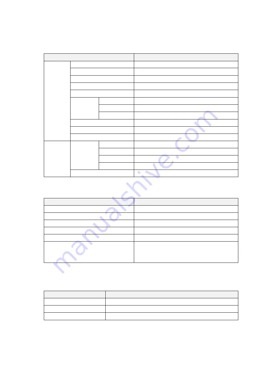
Function Specification 

Items 

Specifications 

LCD Panel 

Method 

TFT Active Matrix Method 

Resolution 

800(W)x480(H) pixels WVGA 

Display Area 

152.4mm(W)×91.44mm(H) 

Pixel Pitch 

0.0635mm(W)×0.1905mm(H) 

Color 

App. 260K colors 

View Angle 

(Typ.) 

Vertical 

140

o

(80

o

/60

 o

Horizontal 

160

o

(80

o

/80

 o

Direction 

From 12 

o’clock direction    (Gray Inversion) 

Brightness (Typ.) 

310 cd/m

2


Backlight   

LED 

Backlight Life (Typ.) 

70,000 hours average

1


Input Signal 

Analog 

SYNC 

2.0 to 

5.5V 2.2KΩ 

RGB 

0 to 0.7Vp-

p / 75Ω 

Horizontal Freq. 

24KHz to 80KHz 

Vertical Freq. 

50Hz to 75Hz 

Digital 

DVI 1.0 Compliant 

1


Time until brightness declines 50% from the initial value at maximum brightness (at ambient temperature of 25

). 


4-2 


Touchpanel Specification 

Item 

Specification 

Type 

Projective Capacitive 

Input Method 

Finger 

Maximum Simultaneous Input 

Two points 

Operating Life 

Continuous Typing (finger input) : 50 million times 

Communication Method 

USB 2.0


Complying OS

※1


Microsoft® Windows® 7 (32bit/64bit) 

Microsoft® Windows® 8/8.1 (32bit/64bit) 

※2


Microsoft® Windows® 10 (32bit/64bit) 

※1 

Windows Standard can be used with touchscreen driver. (Windows 7/8/8.1/10) 

※2 

Operation confirmation made with two point touch and gesture operations. 


4-3 


General Specification 

Item 

Specification 

Rated Voltage 

12V DC 

Permissible Voltage Range 

12VDC ± 10% 

Power Consumption 

MAX 7W 

Summary of Contents for TM Series

Page 1: ...onitor Panel Mount Type Product Specification 7 Wide TMG W207 1211 01 Seedsware Corporation http www seedsware co jp global Contents in this document may change without prior notice Please obtain the delivery specification for the latest design ...

Page 2: ...nnectors Ports 6 5 1 DVI Digital Video Input 6 5 2 Touchscreen Interface USB 6 6 Main Functions 7 6 1 Multi Scanning 7 6 2 OSD Function 7 6 3 Support Signal Timing 7 7 Installation 8 7 1 Mounting Conditions 8 7 2 How to Mount 9 7 2 1 Installng to Panels 9 7 2 2 Attaching to VESA Standard Arms 10 8 Compatible Standards 11 8 1 UL Standards 11 8 2 RoHS Directives 11 8 3 FCC 11 9 Warranty 12 9 1 Warra...

Page 3: ...c preinstalled to unit AC Adapter 1set w AC cord Installation Guide 2 pcs 1 English version and 1 Japanese version Packaging List 2 pcs 1 English version and 1 Japanese version Caution The unit is shipped with the protection sheet already installed to the front side display Be sure to take the sheet off before installing The protection sheet may cause a drop in quality of the surface of the touchs...

Page 4: ...Hz to 75Hz Digital DVI 1 0 Compliant 1 Time until brightness declines 50 from the initial value at maximum brightness at ambient temperature of 25 4 2 Touchpanel Specification Item Specification Type Projective Capacitive Input Method Finger Maximum Simultaneous Input Two points Operating Life Continuous Typing finger input 50 million times Communication Method USB 2 0 Complying OS 1 Microsoft Win...

Page 5: ...stance of 100Ω 2mm 2 0 0062inch 2 or thicker wire or your country s applicable standard Structure Protection Structure IP65 1 Only front display side at panel mount Cooling Method Natural Convection External Dimension 192 W x 137 H x 36 D mm Weight App 700g Panel cut out dimension 183 5 0 5 0 W x 128 5 0 5 0 H mm 1 Protection structure of front area when mounted to panel The degree of protection p...

Page 6: ...I Connector 5 Touchscreen Interface USB USB Type B Connector Dial Switch Operations Power ON OFF Push dial switch to turn the monitor ON Push and hold for more than 2 seconds to turn the monitor OFF Leave an interval of 5 seconds when repeatedly turning the power ON and OFF OSD Operation Push the dial switch when the touchscreen is ON to display the OSD Turn the switch clock wise or counter clock ...

Page 7: ...1 GND 21 NC 2 DATA2 12 NC 22 GND 3 GND 13 NC 23 CLKa 4 NC 14 DDC 5V 24 CLKa 5 NC 15 GND C1 Analog RED 6 DVI_DDC_SCL 16 GND C2 Analog GREEN 7 DVI_DDC_SDA 17 DATA0 C3 Analog BLUE 8 NC 18 DATA0 C4 Analog H Sync 9 DATA1 19 GND C5 Analog GND 10 DATA1 20 NC 5 2 Touchscreen Interface USB Interface USB 2 0 Connector USB type B Pin No Signal Pin No Signal 1 Vbus 3 D 2 D 4 GND ...

Page 8: ...ion Adjust horizontal position of display V Position Adjust vertical position of display Clock Fine adjustment of horizontal position of video input Phase Adjustment of phase Exit Go back to main menu Color Temp 9300K 7500K 6500K User Color User adjust intensity of colors red green and blue Auto Color Adjust automatically color level of input signal sRGB Exit Go back to main menu Language Choose a...

Page 9: ...ranges Ambient operation temperature indicates both the display side and inside of cabinet where the TM will be installed Ambient temperature is for both inside the cabinet and panel face TM should be mounted perpendicular but if it should be mounted in an angle the angle shall not be more than 30degrees from the vertical position shown in the illustration below 30 or less When installing the TM i...

Page 10: ... 5 0 0 5 4 R3以 下 The material of the mounting panel please use the metal Be recommended panel thickness range depending on material and size may not maintain the strength when an impact is applied Please do take into account such as reinforcement in the environment impact such as join There is a possibility of personal injury or product damage when dropped product Please be careful not to drop ...

Page 11: ...rm stand or apparatus that is listed to comply with the UL1678 standard Please refer to each arm or stand manual for attaching directions Dimensions of the installation holes are as shown in below diagram Use M4 screw at torque range of 0 7Nm to 0 8Nm when attaching Select M4 screws so it is 6mm or less in depth from the rear side of the TM case 75 mm 75 mm ...

Page 12: ...o comply with the limits for a Class A digital device pursuant to Part 15 of the FCC Rules These limits are designed to provide reasonable protection against harmful interference when the equipment is operated in a commercial environment This equipment generates uses and can radiate radio frequency energy and if not installed and used in accordance with the instruction manual may cause harmful int...

Page 13: ...static electricity 4 If the product is used under any condition in any environment or by any method other than those specified in the specifications catalogs manuals notes and or other documents 5 Any replacement of consumables 6 Any malfunctions defects and or damages caused by associated equipment and or usage of inappropriate consumables and media 7 If the product is repaired remodeled modified...

Page 14: ...0 are trademarks and registered trademarks of Microsoft Corporation USA in the United States and other countries Other company and or product names listed herein are also trademarks and or registered trademarks 3 rd Edition January 2017 USCO America Inc 136 W Valletts Street Elmhurst IL 60126 USA Phone 630 832 0438 510 931 9046 E mail sales uscoamerica com Business hours 9 00a m 5 45p m Central Ti...

Page 15: ...ct Label 4 M4 ネジ侵入深さ6mm以下 Effective Screw Depth 6mm 183 128 75 75 寸法許容差 TOLERANCE 呼び寸法 Nominal Dimensions L 3 10 L 18 18 L 30 6 L 10 30 L 50 0 4 0 58 0 7 0 84 1 0 0 48 3 L 6 50 L 80 80 L 120 120 L 180 180 L 250 250 L 315 315 L 400 400 L 500 1 2 1 4 1 6 1 85 2 1 2 3 2 5 状態表示LED Status Display LED 137 2 NOTES 1 誤動作の恐れがある為 パネル開口寸法をお守り下さい 又 取付けパネルには 反り 傷 凹凸のないものを使用して下さい To prevent malfunctions pane...

Reviews: