background image

    BREEZAIR EXQ/EZQ/EXS EVAPORATIVE COOLERS INSTALLATION MANUAL  

|  

13


ILL1648-A

A

C

D

E

B

ILL746-E

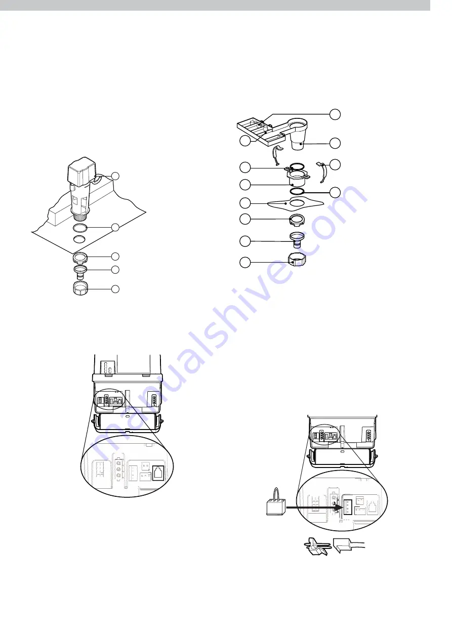
A  Drain Valve
B O-Ring
C Nut
D  Drain Adaptor
E  Lock Nut

A Ribs
B O-Ring
C  Threaded Bush
D  Tank (Reservoir)
E Nut
F  Drain Adaptor
G  Lock Nut
H  Removable Nut
I  Bleed Tray
J  Spring Clip
K O-Ring

A

B

C

D

E

F

G

H

I

J

K

ILL1410-C

ILL1362-B

INSTALLING THE DRAIN VALVE OR  


BLEED TRAY

Water drained from the cooler must be carried away to a 

suitable discharge point in accordance with local regulations.

Important!

 Never drain water from the cooler directly on to the 

roof.

Make sure the o-ring (C) is fitted before placing the drain valve 

into the hole. Screw the nut (E) up tightly by hand underneath 

the cooler.

Important!

 Do not over-tighten plastic fittings.

Connect the drain valve cable to the cooler electronics box.

HARMONY AND HORIZON  

DRAIN VALVE ASSEMBLY

Assemble the drain valve as shown:

HOMEMAKER BLEED TRAY

Fit the bleed tray as shown:

Screw the nut up tightly by hand underneath the cooler.  

Do not overtighten.
Note! 

Make sure the bleed tray is correctly oriented (the bleed 

tray must sit underneath the Chillcel pad when it is fitted) and 

that the o-rings are fitted before placing the threaded bush into 

the hole.
The bleed rate is controlled by the number of plugs that are 

inserted into the tray. The more plugs inserted, the more water 

will bleed off. 

Important! 

For Homemaker models, the water probes and 

inlet solenoid cable must be removed and discarded. The 

supplied shorting plug must be fitted to the electronics module 

(before the power is turned on), where the water probes were 

connected (A).

Correct Plug Orientation

Failure to fit the shorting plug will result in the pump not 

operating.

Summary of Contents for Breezair EXQ

Page 1: ... English INSTALLATION MANUAL EXQ EZQ EXS Evaporative Coolers ILL1672 A Original English Instructions ...

Page 2: ...NG THE MAGIQTOUCH CONTROLLER 14 COMMISSIONING THE COOLER 14 DIAGNOSTIC LED 14 SALINITY LED 14 MAGIQTOUCH CONTROLLER INFORMATION 15 TESTING THE DIRECT DRIVE MOTOR 15 SETTING THE WATER LEVEL 15 TESTING THE DRAIN VALVE 16 REFITTING THE PAD FRAMES 16 TESTING THE PUMP 17 ADJUSTING COOLER SETTINGS 17 COMMISSIONING COMPLETION CHECKLIST 18 TROUBLE SHOOTING GUIDE 19 WARNING Failure to install and commissio...

Page 3: ...lty how can they summon help Call someone on the ground Mobile phone etc What condition is the roof in Should the trusses underside or surface be checked Does the worker have appropriate foot wear Flat sole jogger type is advisable Are all power cables extension leads safe and appropriately rated Are all ladders tools and equipment suitable in good condition Where ladders are to be used is there a...

Page 4: ...nt cooler to the dropper Check tank is level STEP 14 COMMISSION COOLER Test the cooler with the MagIQtouch Controller Check diagnostics of cooler electronics Test Direct Drive motor STEP 20 CLEAN UP Clean up the site STEP 3 PREPARE DROPPER Cut hole fit grommet in dropper for cables STEP 8 WEATHERDAMPER Check operation of the weatherdamper STEP 15 WATER LEVEL DRAIN Set the water level Test drain va...

Page 5: ...ng manually STEP 11 INLET SOLENOID Fit solenoid Connect cable Connect water supply Install drain pipe STEP 17 TEST PUMP Turn on cooler and check water is evenly distributed to all pads STEP 6 POWER CABLES Unhook the plug under the cooler Feed power cable down into dropper STEP 12 DRAIN VALVE Fit the drain valve Connect discharge system Connect cable to cooler electronics STEP 18 COOLER SETTINGS Wh...

Page 6: ...Always locate the cooler where it will receive adequate fresh air and not in a recess where it may be starved for air or where the air is polluted Ensure location is a minimum of 3m from a solid fuel heater flue 1 5m from a gas flue 5m from a sewer vent and 600mm from a wall The cooler must be mounted at least 3m preferably 5m away from any TV antenna or antenna cables Make sure the cooler is not ...

Page 7: ...r then fit and screw the cable grommet into position Locate the hole so the cables will not interfere with the operation of the weather damper Before transporting to the roof temporarily screw the transition to the dropper using a screw in each corner Affix gauge timbers under the top and bottom edges of the transition with 30mm screws supplied Keep the pallet to create a gauge for locating the tr...

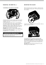
Page 8: ... 3 sides This may require the addition of extra structural timber MOUNTING THE DROPPER Important The dropper must never sit directly on any ceiling joists or beams as this may cause noise or vibration issues and possible ceiling damage LEVELLING THE DROPPER TRANSITION Ensure the top of the dropper or transition for EZQ model is level and square in all directions use a spirit level This helps with ...

Page 9: ...ate the cooler on the dropper with the tank sump on the low gutter side of the installation Also remove the lower pads as they may fall out when transporting the cooler to the roof CONVEYING THE COOLER TO THE ROOF Lifting and installing the cooler is made easier by removing the pad frames first They can be replaced at the very end of the installation procedure Do not slide the cooler lift and carr...

Page 10: ... the roof squeeze the latch and rotate it clockwise to its operating position The weatherdamper latch performs two functions In the locked position it acts as a latch preventing movement during transport Important Ensure that the four Tab Screws which are removed to separate the transition from the cooler are re fitted behind the tabs after the cooler has been fitted into position Carefully lift t...

Page 11: ...Water Connection BSP Min Water Pressure 100 kPa 15 psi Max Water Pressure 800 kPa 115 psi Min Water Flow 8 litres min Max Water Temperature 40 C Important If the water pressure exceeds maximum specification then a pressure reducing valve is required and must be supplied and fitted by the installer Harmony Horizon For Coolers with the inlet solenoid valve fitted the water connection is a 1 2 BSP co...

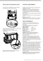
Page 12: ...ank so it does not get trapped by the solenoid cover when fitted The cable leads can be connected to the solenoid either way around Important The cable must wrap underneath the solenoid Fitting the Solenoid Cover Once the solenoid valve and its cable has been fitted place the cover over the assembly Make sure the solenoid valve cable is retained in the groove in the cooler tank Secure the cover by...

Page 13: ... Connect the drain valve cable to the cooler electronics box HARMONY AND HORIZON DRAIN VALVE ASSEMBLY Assemble the drain valve as shown HOMEMAKER BLEED TRAY Fit the bleed tray as shown Screw the nut up tightly by hand underneath the cooler Do not overtighten Note Make sure the bleed tray is correctly oriented the bleed tray must sit underneath the Chillcel pad when it is fitted and that the o ring...

Page 14: ...le through our Sales order office and spare parts outlets in the following lengths Part No Length Details 833880 20m MagIQtouch Controller Cable No Ferrite 823553 20m MagIQtouch Controller Cable EXQ EXS With Ferrite 862873 1 5m MagIQtouch Controller Cable No Ferrite 861265 3m MagIQtouch Controller Cable No Ferrite 864396 30m MagIQtouch Controller Cable EXQ EXS With Ferrite 864402 40m MagIQtouch Co...

Page 15: ... the screen as they occur Current cooler operation information can be temporarily displayed on the Status Information Display option in the GENERAL SETTINGS menu When this option is turned on a temporary information display window becomes accessible on all MANUAL and PROGRAM screens TESTING THE DIRECT DRIVE MOTOR This Breezair cooler incorporates a Seeley electronically commutated Direct Drive Mot...

Page 16: ...be tested from the Service Operating Screen Set DRAIN to ON to energise the component and close the drain Set DRAIN to OFF to open the drain Alternatively the Manual Drain option in the COOLER SETTINGS menu can be used REFITTING THE PAD FRAMES Refit the pad frames by locating the bottom edge in the tank groove then push the top in under the lid Refit the corner clips after replacing the pad frame ...

Page 17: ...hen return to the set fan speed Prewet When COOL mode is activated the pump will run for 90 seconds before the fan is switched on Salinity Level Sets the salinity level at which the tank will drain in SALINITY MEASUREMENT mode Tank Drain Delay Sets the time delay before the drain valve opens after the pump in the cooler is turned off Autoclean Select the preferred cleaning interval 50 100 200 hour...

Page 18: ...ode ensure all pads have even water saturation and there are no visible water leaks COOLER SECURE The cooler is secure and level on the dropper using all fixings supplied SEALED The dropper and all penetrations are correctly flashed and sealed WEATHERDAMPER OPERATES The weatherdamper operates correctly and can open and close without interference PLUMBING FLUSHED The water pipes were flushed of any...

Page 19: ...ia the tri colour LED on cooler electronics box Rectify fault as indicated and restart the cooler MagIQtouch Controller failure Replace MagIQtouch Controller Pump runs but no water circulation Pump runs but pads lack water Insufficient water in tank Adjust float level Water hoses blocked Check and clean out blockage Pump strainer blocked Clean pump strainer Insufficient water supply pressure Check...

Page 20: ...rnational com service Spare Parts Information To identify and order spare parts for Seeley International products online go to seeleyinternational com get support spare parts It is the policy of Seeley International to introduce continual product improvement Accordingly specifications are subject to change without notice Please consult with your dealer to confirm the specifications of the model se...

Reviews: