8
|
The installer must ensure the dropper is suitable, and is
secured adequately for wind conditions at the site. Additional
restraints may be required if the cooler is more than 200mm
higher than the roof timbers, or design wind velocity at the site
exceeds 43m/s.
In exposed or very high wind areas use 16 screws, minimum
shank diameter 5.2mm to secure the dropper. In areas subject
to cyclones or where the cooler is located more than 8m above
the ground seek advice from a structural engineer.
Important!
Ensure the weather damper operation is not
hindered by the attaching screws.
EXQ/EXS MODEL
EZQ MODEL
ILL1647-A
ILL182-H
EXTRA NOTES FOR EZQ MODEL ONLY
EXTRA NOTES FOR EZQ MODEL ONLY
EXTRA NOTES FOR EZQ MODEL ONLY
Fit & secure the transition to the top of the dropper,
repeating the same fixing rationals for exposed, high
wind areas, cyclones etc.
Important!
The flashing should go up, but not higher
than 20mm above the bottom of the transition and may
not add more than 7mm girth to the dropper including
fasteners. This ensures a neat installation.
The dropper may now be flashed to the roof. Make sure there is
no chance of water entering the roof space.
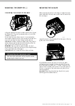
Install the dropper and securely fix it to the roof structure on 3
sides. This may require the addition of extra structural timber.
MOUNTING THE DROPPER
Important!
The dropper must never sit directly on any ceiling
joists or beams, as this may cause noise or vibration issues,
and possible ceiling damage.
LEVELLING THE DROPPER / TRANSITION
Ensure the top of the dropper (or transition for EZQ model) is
level and square in all directions (use a spirit level). This helps
with levelling the cooler.
ILL2129-A
Ensure duct insulation is firmly held in against the duct.
SECURING THE DROPPER & TRANSITION
Place level vials in side wells provided in the transition.
Pivot the transition/dropper off the appropriate gauge
timber (top or bottom) until the level reads true. Hold
dropper in place using one single screw into the rafter.
This will set dropper at an angle of 24°. Check for lateral
level by placing level vials in top or bottom wells.
Note!
Very few roof slopes will contact both gauge timbers
once the dropper is properly levelled. As a general rule:
• For roof angles less than 26°, only the bottom gauge
will apply.
• For roof angles greater than 26°, the top gauge will be
used.
This will be apparent when checking for level via the
level vials.
Note!
The height gauges are intended to work off the
top nominal surface of the roof. Uneven roof surface
e.g. Tiles may require some packing up.
Once the dropper is secured, remove the gauges and
transition so that the dropper can be sealed.
SEALING THE DROPPER


