background image

(English) (CW-H15)

INSTALLATION & OPERATION MANUAL

INDIRECT EVAPORATIVE COOLER 

CW-H10, CW-H15, CW-H15S, CW-H15S Plus

Original English Instructions

ILL2468-A

Summary of Contents for Climate Wizard CW-H10

Page 1: ... English CW H15 INSTALLATION OPERATION MANUAL INDIRECT EVAPORATIVE COOLER CW H10 CW H15 CW H15S CW H15S Plus Original English Instructions ILL2468 A ...

Page 2: ...1 Local Zone Control with Wall Control 20 Option 2 Building Management System BMS Interface 20 Remote On Off Input 20 Cool Vent Input 20 Fan Speed Input 20 Error Signal Output 20 WALL CONTROL INSTALLATION 21 Locating the Wall Control 21 Fixing the Wall Control Bracket to a Plasterboard Wall 21 Fixing the Wall Control Bracket to a Brick Wall 21 Fitting the Wall Control to the Mounting Bracket 21 Ru...

Page 3: ...mply with all of the maintenance and service requirements set out in this Manual Compliance with these requirements will prolong the life of your cooler Further it is also a condition of warranty cover that each item in the Maintenance Schedule in the Manual is filled out by signing and dating it in the places indicated when the item is completed Any failure to carry out the required maintenance a...

Page 4: ...h prevents employees from working on roofs if they are unwell or under the influence of drugs or alcohol Are there any special conditions to consider i e excessive roof pitch limited ground area fragile roof electrical power lines OTHER IMPORTANT REQUIREMENTS Never force parts to fit because all parts are designed to fit together easily without undue force Never drill holes in the tank s of the co...

Page 5: ...Y INTERNATIONAL INSTALLATION MANUAL 5 COOLER VIEWS Dimensions are in mm inches in brackets ISOMETRIC CW H15 views shown TOP REAR SIDE BOTTOM ILL1916 A ILL1918 A ILL1917 A ILL1919 A ILL1920 A FRONT ILL2422 A ...

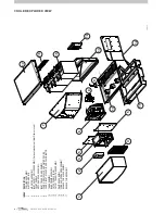
Page 6: ...LLE ASSEMBLY Optional mandatory if Inlet Filter not used 5 FRONT PANELS 6 MOTOR AND FAN ASSEMBLY 7 INLET TRANSITION ASSEMBLY 8 PUMPS DRAIN VALVE AND WATER PROBE 9 PUMPS INLET SOLENOID AND CHLORINATOR 10 TANK ASSEMBLY 11 BASE FRAME ASSEMBLY 12 OUTER PANELS RHS 13 14 15 16 EXHAUST GRILLE ASSEMBLY 17 OUTLET TRANSITION ASSEMBLY DAMPER ASSEMBLY CORE AND SPREADER ASSEMBLY EXHAUST LID ASSEMBLY ILL2423 A ...

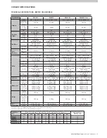
Page 7: ...s 13 L min 1 5m head 230V 50Hz Input power 30W ea 4 pumps 13 L min 1 5m head 230V 50Hz Input power 30W ea 4 pumps 13 L min 1 5m head 230V 50Hz Input power 30W ea Drain 11 2 male BSP 12 V motor 11 2 male BSP 12 V motor 11 2 male BSP 12 V motor 11 2 male BSP 12 V motor Chlorinators 1 chlorinator 1 chlorinator 1 chlorinator 1 chlorinator Air Filters Type G4 washable 305 610 50mm Qty 2 610 610 50 Qty ...

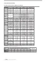
Page 8: ...male NPT 12V Solenoid 1 2 male NPT 12V Solenoid 1 2 male NPT 12V Solenoid Tank 17 gal 17 gal 17 gal Pumps 3 pumps 3 4gal min 4 9 head 220V 60Hz Input power 32W ea 4 pumps 3 4gal min 4 9 head 220V 60Hz Input power 32W ea 4 pumps 3 4gal min 4 9 head 220V 60Hz Input power 32W ea Drain 11 2 male BSP 12 V motor 11 2 male BSP 12 V motor 11 2 male BSP 12 V motor Chlorinators 1 chlorinator 1 chlorinator 1...

Page 9: ...430 120447 Inlet Air Filter Frame inc Filters CW H10 Inlet Air Filter Frame inc Filters CW H15 H15S H15S Plus Bushfire Rated Inlet Air Filter Frame inc Filters CW H10 Bushfire Rated Inlet Air Filter Frame inc Filters CW H15 H15S H15S Plus 3A 3B 120416 120386 Inlet Air Filter Cowling CW H10 Inlet Air Filter Cowling CW H15 H15S H15S Plus 4 094724 Control Cable 40M 5A 5B 134192 134215 Roofstand 0 10O...

Page 10: ...g of installation components along with the exhaust transition side rails and grilles can be found under the lid of the main cabinet of the cooler The exhaust transition will need to be raised into place before operation The wall control and communications cable along with ancillary mount plates fasteners and drain adaptors will need to be placed aside for later connection WARNING Once unwrapped t...

Page 11: ...ails sitting on the tops of the cooler side walls and the end posts sitting on the outside of the front tray ILL2428 A 6 Slip the 2 x EXHAUST GRILLE and 1 x EXHAUST CENTRE POST into position retained inside the top panel front u channel CW H15S Plus ONLY Before fitting to the cooler slide an EXHAUST CAP over the back of each EXHAUST GRILLE The EXHAUST CAP covers the top portion of the EXHAUST GRIL...

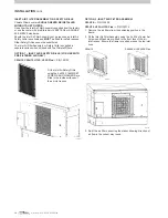
Page 12: ... INLET AIR SAFETY GRILLE FOR USE WITH PRE FILTERED AIR ONLY CW H10 CW H15 H15S H15S Plus P N 120102 OPTION 2 INLET AIR FILTER ASSEMBLY CW H10 P N 120409 CW H15 H15S H15S Plus P N 120379 1 Remove the air filters from their shipping position in the frame 2 Fit the Inlet Air Filter Assembly using the 4 x M6 x 16mm Set Screws and Washers pre fitted to the front face of the air inlet recess Ensure the ...

Page 13: ...mets fitted to the cooler body 4 Screw the cowling side panel and the top panel to the cooler body with supplied 6 x SCREW SEMS HEX 14 x 3 4 ZP 5 Fit the supplied 2 x quarter turn self ejecting fasteners to the Cowling Front Panel Ensure the supplied split washer is fitted as shown b CW H10 Fit the right hand side panel as above Fit the left hand side panel using the same pre fitted M6 x 16mm Set ...

Page 14: ... water that is suitable to be classified as potable and fit for human consumption If alternative water including rain water is to be used that contains high levels of salinity hardness acidity or chemical contaminants then additional filtration or treatment systems should be employed to render the water potable WATER HAMMER Not all installation pipeworks are the same and some may require additiona...

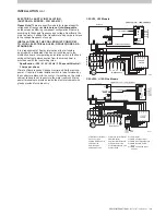
Page 15: ...al 3 Amps per phase Climate Wizard requires 3 phase Neutral and Earth electrical power If required mains isolation switch is to be furnished by the contractor adjacent to the cooler if mounting on the cooler cabinet take care not to puncture the water reservoir Mains power terminals are provided inside the electrical cabinet with glands provided for cable entry 859651 E MAIN PCB C1 C2 C3 C4 C5 C6 ...

Page 16: ...e electrical cabinet with glands provided for cable entry 860312 D MAIN PCB 230Vac INPUT 12Vdc OUTPUT DENOTES CLASS 2 CIRCUIT CLASS 2 POWER SUPPLY MPS 30 12 C1 C2 C3 C4 C5 C6 C7 C8 C9 C10 C11 C11 C13 C13 C10 C12 C12 C4 C17 C16 C15 C14 100VA TRANSFORMER 380 480V TO 230V BMS CONTROLS FAN CONTACTOR INTERFACE PCB T1 T2 T3 T4 T5 T6 T7 L3 L2 L1 A1 5 3 1 2 4 6 A2 gn y gn y CHLORINATOR PUMP JUNCTION BOX M...

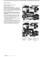
Page 17: ...CE BOARD LINK C12 NOT USED C13 CHLORINATOR C14 BMS COOL VENT INPUT C15 BMS ERROR SIGNAL OUTPUT C16 BMS REMOTE ON OFF INPUT C17 BMS FAN SPEED INPUT 0 10Vdc 861371 C MAIN PCB 230Vac INPUT 12Vdc OUTPUT DENOTES CLASS 2 CIRCUIT CLASS 2 POWER SUPPLY MPS 30 12 C1 C2 C3 C4 C5 C6 C7 C8 C9 C10 C11 C11 C13 C13 C10 C12 C12 C4 C17 C16 C15 C14 BMS CONTROLS FAN CONTACTOR INTERFACE PCB T1 T2 T3 T4 T5 T6 T7 L3 L2 ...

Page 18: ...K C11 INTERFACE BOARD LINK C12 NOT USED C13 CHLORINATOR C14 BMS COOL VENT INPUT C15 BMS ERROR SIGNAL OUTPUT C16 BMS REMOTE ON OFF INPUT C17 BMS FAN SPEED INPUT 0 10Vdc MAIN PCB 230Vac INPUT 12Vdc OUTPUT DENOTES CLASS 2 CIRCUIT CLASS 2 POWER SUPPLY MPS 30 12 C1 C2 C3 C4 C5 C6 C7 C8 C9 C10 C11 C11 C13 C13 C10 C12 C12 C4 C17 C16 C15 C14 BMS CONTROLS FAN CONTACTOR INTERFACE PCB T1 T2 T3 T4 T5 T6 L2 L1...

Page 19: ... 1 Connect a 24VDC power supply on to terminals 7 8 of the 24VDC Relay inside the Coolers Control Box 2 Wire a switch in series to the one of the conductors to the 24VDC Relay 3 Locate the Switch next to the Cooler s Wall Control 8 7 5 3 RELAY 24VDC SUPERCOOL PUMP SWITCH FAN MOTOR 24VDC POWER SUPPLY ILL2445 A ILL2445 A RELAY CONTROL METHOD 2 BMS 1 Connect a 24VDC power supply on to terminals 7 8 o...

Page 20: ... achieve group control is possible OPTION 2 BUILDING MANAGEMENT SYSTEM BMS INTERFACE Climate Wizard coolers are supplied with an Interface PCBA in the electrical control enclosure This can be set up to control the Climate Wizard from EXTERNAL devices such as PLCs or Building Management Systems and requires an independent low voltage power supply supplied by the installer Note Even if a BMS or PLC ...

Page 21: ...ARD WALL Use the bracket as a template 1 Drill the 16mm 5 8 hole for the wall control cable 2 Drill the 5mm 3 16 holes for the wall plugs 3 Insert the wall plugs into the holes Align and screw the bracket into position using the supplied screws WALL CONTROL INSTALLATION FIXING THE WALL CONTROL BRACKET TO A BRICK WALL To mount the wall control bracket on a brick wall follow the previous instruction...

Page 22: ...ent water take off from the cores entering either the exhaust air stream or the cooled air stream and the building ducting slowing only occurs if the fan was running above the safe watering speed limit Salinity Control Water Conductivity sensing Measures water conductivity for 10 seconds within every minute When conductivity exceeds the upper set point the water inlet solenoid valve is opened to a...

Page 23: ...e 4 To alter the value of selected parameter press or Numbers will change to show different values parameter can be set to 5 To store the selected value press Screen will go blank momentarily as wall control stores parameter change and returns screen to A and Param 6 To exit parameter mode or escape from an alteration without storing a change press button instead of button Remember once step 5 has...

Page 24: ...ter tubes for measuring pressure NOTE Pressure measuring should be carried out using an accurate instrument either electronic or inclined tube manometer DO NOT GUESS ILL2447 A ILL2447 A 1 Fit Climate Wizard Inlet Air Filters and Cowling if required 2 Connect all external supply and exhaust ductwork 3 Fully open all supply air outlets in the entire ductwork system 4 Cold Front or Supplementary Cool...

Page 25: ...ase of an emergency All ducts are fixed correctly and there are no air leaks The system has been run from the customer s wall control and all functions work correctly The air balance for all outlets has been adjusted to the customer s satisfaction The customer has been shown how to operate the system All the installation rubbish has been removed and if applicable any property damage repaired COMMI...

Page 26: ...n the day s conditions Pressing or button will change the displayed room temperature to a flashing setpoint temperature This setpoint temperature can be adjusted by pressing the or buttons whilst the setpoint temperature is being displayed ILL1710 A Cool Auto DELAYED START AND STOP The cooler can be programmed to start at a specific time or stop at a specific time The delayed start time can only b...

Page 27: ...f 04 is displayed 1 Check that the drain is not blocked If these do not fix the problem then contact your Service Agent You will need to quote the flashing number that you wrote down DRAIN MODE Cooler switched OFF Pressing the and buttons at the same time for 2 seconds will open the drain valve and empty the water in the reservoir The wall control will display dr on the screen Draining the water w...

Page 28: ...s securing the pump bracket to the wall of the cooler 3 Disconnect the plumbing hose from the spigot at the pump base 4 Remove the pump assembly from the cooler cabinet 5 To remove pump from the strainer press the release button on the strainer twist the pump body clock wise with button depressed and lift the pump body out of the strainer base Note the orientation prior to removal 6 Inspect and cl...

Page 29: ...ket pull the lead through the opening in the bracket and pull the probe out from the enclosure there is sufficient lead length to clear the pump enclosure Remove the small plastic shrouds from the first and third pins 3 Clean the pins by wiping the contact surfaces with a soft cloth do NOT use abrasives 4 Check the probe pin resistances using a multi meter refer figure and wiring diagram you ll ne...

Page 30: ...A 2 1 3 5 4 6 1 DRAIN VALVE ASSY 2 O RING 3 NUT 4 ELBOW SPACER 5 DRAIN ELBOW 6 POSITIVE PRESSURE TUBE NUT SPACER ELBOW DRAIN VALVE ACCESS PANEL ILL2453 A SOLENOID VALVE MAINTENANCE AND REPLACEMENT No regular maintenance of the solenoid valve is required SIDE VIEW LHS ILL1954 B ILL1954 B Pump Access Panel Solenoid Valve Replacement Only 1 Turn off the water supply 2 Remove the breather hose from an...

Page 31: ...t the larger front filter locate the top edge of the filter under the top brackets and lift to engage the filter inside them Allow the filter to drop to engage the 2 bottom brackets at the bottom of the frame Model CW H10 CW H15 H15S H15S Plus Replacement Kit P No 120423 120393 Kit Contents 1 24x24x2in 594x594x45mm 2 24x12x2in 594x291x45mm 1 24x24x2in 594x594x45mm 3 24x12x2in 594x291x45mm ILL2455 ...

Page 32: ...tation Side View Top View REAR REAR FRONT FRONT ILL2458 A CHANGING COOLER CORES ORIENTATION ILL2458 A 10 Check the cores fit snugly and squarely across the width of the core platform and are firmly butted together Check for a uniform gap at either side of the cooler between the side walls and the core The core access door has a seal to take up any resultant gap Locate the flange of the spreader ho...

Page 33: ... recommended to remove the pad on the far left first CHILLCEL RETENTION RAIL LIFT TO REMOVE STEP 2 WATER SPREADERS ILL2463 A 4 To re assemble first position the top of the far right pad underneath the spreader and push the base of the pad into place before sliding the pad into its final position 5 Note the chillcel pad has a small header block this is the top of the chillcel pad and must be positi...

Page 34: ...ge to the word Value this indicates the fault code number that occurred 4 Press button to return to the original F1 and Param display 5 Use buttons or to scroll through the fault log 6 Fault indicators F1 to F4 are the last four faults that were recorded by the CPMD and they might get repeated if the fault has re occurred Fault indicators FA to Fd are the last four types of faults that have occurr...

Page 35: ...he Supply Air Discharge Damper procedure on Setting the Air Discharge Damper on page 24 Check spreader assemblies securely clamped to top of cores and gaps between cores covered up Check core doors correctly sealing against sides of cores MAINTENANCE INSTRUCTIONS cont LED Wall Control Fault Code Fault Description Suggested Remedy 2 Green Flash then 2 seconds off NORMAL OPERATION 1 Red Flash then 2...

Page 36: ...ation isolation Access Installation Date 03 29 1980 Installer It is a condition of your warranty cover that the items in the schedule below are checked and action taken as required once every 3 months from the date of installation by a qualified licensed technician and that the schedule is properly filled out i e name signature date action taken Note that Air inlet filters must be inspected and cl...

Page 37: ...readers Water level Cabinet and Accessories Cabinet integrity leaks Air inlet Air inlet filters 1st month of quarter Air inlet filters 2nd month of quarter Air inlet filters 3rd month of quarter Tank Fan Impeller inlet cone alignment General Operation Start up and run sequence Control operation Air outlet vane setting indicate setting in Pa General Installation Electrical connections Water connect...

Page 38: ...f quarter Tank Fan Impeller inlet cone alignment General Operation Start up and run sequence Control operation Air outlet vane setting indicate setting in Pa General Installation Electrical connections Water connections Duct condition Roof penetrations Mounting Vibration isolation Access Service No Service Date Service Technician Service Company No 9 No 10 No 11 No 12 To Owner User please note tha...

Page 39: ...20m 65 Control Cable 40m 131 12A 12B 120423 120393 Air Filters CW H10 Air Filters CW H15 H15S H15S Plus 13A 13B 13C 13D 13E 13F 13G 13H 13I 13J 13K 13L 13M 094373 094335 094366 094380 094397 093963 TBC 093956 093970 093994 TBC TBC TBC Smartcard H10 380 480V 3 Smartcard H15 380 480V 3 Smartcard H15 380 480V 3 HIGH ALTITUDE Smartcard H15S Plus 380 480V 3 Smartcard H15S 380 480V 3 Smartcard H15 200 2...

Page 40: ...___________________ Installation Address _________________________________________________________ Installation Type Residential Non Residential Commercial Date of installation _________________________________________________________ Installer Dealer _________________________________________________________ As with any product that has moving parts or is subject to wear and tear it is VERY IMPORT...

Page 41: ...es but it is not limited to electrical surges and inadequacies failure or other problems in or with any electricity power or water supply to the Goods c after the first year the replacement supply or servicing of consumable items including without limitation washers seals and drive belts d despite clause 2 c above the air filters and e installation including without limitation ductwork fittings an...

Page 42: ...s then they must be accompanied by a covering letter which states your name and address and daytime telephone number the address at which the Goods are installed and the model and serial number of the Goods 8 The warranty granted in clause 1 covers the costs of parts and labour but you will be responsible for a the cost of travel incurred for a Seeley International service agent to get to and from...

Page 43: ...provide us with to provide warranty support for the product you have purchased and to inform you about other products and services If you choose not to supply us with the information requested we may be unable to provide you with warranty support We may also disclose your information to third parties such as related entities retailers distributors service agents and contractors who are affiliated ...

Page 44: ...ernational Pty Ltd 112 O Sullivan Beach Road Lonsdale SA 5160 Australia MANUFACTURED BY Seeley International Pty Ltd 77 North Street Albury New South Wales 2640 Australia for Australia Europe and South Africa Seeley Acquisition Co Ltd doing business as Coolerado 4430 Glencoe Street Denver Colorado 80216 USA for the USA and the Americas IMPORTED BY Seeley International Europe Limited Unit 11 Byron ...

Reviews: