CW-H COOLER PLC OWNER’S MANUAL 859731-D
|
1
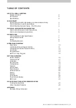
TABLE OF CONTENTS
CW-H PLC WALL CONTROL
Models: All CW-H
2
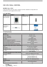
Kit Contents
2
Specifications
2
QUICK START
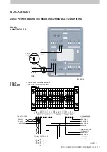
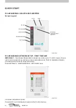
24Vdc Power And RS 485 Modbus Communications Wiring
3
RS 485 Modbus Cooler Node Address
4
RS 485 Modbus Network Setup - First Time Use
4
PHYSICAL DESCRIPTION & MOUNTING
Wall Control Dimensions And Setup Notes
5
Wall Control Installation Instructions
6
CONNECTING
Communication Cable Specification
7
Wiring Requirements
7
Power 8
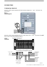
Terminating Resistor
9
OPERATION SCREENS
Main Menu
10
Cool Mode (Manual Speed Control)
11
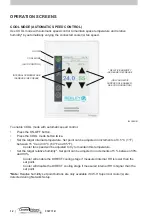
Cool Mode (Automatic Speed Control)
12
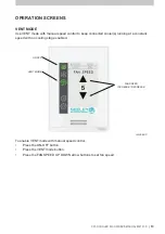
Vent Mode
13
Program Mode
14
Edit The 7-Day Program
15
SETTING SCREENS
Screen Display
16
Time And Date
17
Language
17
Security Lock
18
Configuration
18
Network
19
Auto-Restart
20
Room Sensor
20
Ambient Sensor
20
Device
21
Monitor
21
Fault History
22
Fault Screen Display
23
BMS Lock
24
COOLER FAULTS AND TROUBLESHOOTING
Troubleshooting Table
25
Other Potential Problems
26
APPENDIX
Example Wiring Schematic
27
Summary of Contents for CW-H 2020 PLC
Page 1: ...OWNER S MANUAL CW H 2020 PLC WALL CONTROLLER English Original English Instructions ILL2468 A ...
Page 2: ......
Page 30: ...28 859731 D ...
Page 31: ......

