


Rostock MAX v2 Assembly Guide – 4thEd.
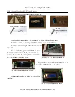
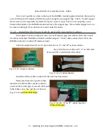
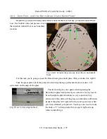
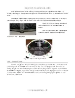
04May16 – Note that if your LCD panel has a red or blue PCB, it will connect to the
interface board as shown in Figs. 17.10-3B and 17.10-3C.
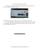
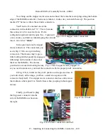
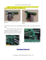
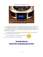
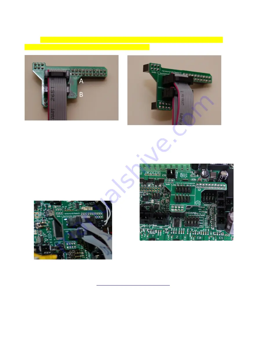
Install the LCD interface board on to the RAMBo controller as shown. Wiring has been omitted for
clarity.
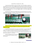
Make sure that the interface adapter board
is properly seated on the RAMBo board – it is
possible to set the board down offset one row to
the left or right and the LCD will not function.
Checkpoint Video #22
17 – Installing & Connecting the RAMBo Controller – 132
Fig. 17.10-4: LCD interface adapter installed.
Fig. 17.10-5: Install complete!
Fig. 17.10-3B: Red or Blue Display PCB
cabling.
Fig. 17.10-3C: Red or Blue Display PCB
cabling.


