


Rostock MAX v2 Assembly Guide – 4thEd.
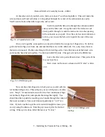
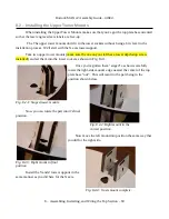
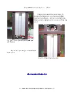
Now carefully set the end of the tower in the opening and slide it in. It's a VERY tight fit but do
not wiggle it! You want to drive the tower straight down. If you wiggle it front to back too much, you
can break the area where it's thin at the corners of the hole.
As you drive the tower down, make sure that the T-Slot nut plates are sliding into the t-slots on
both sides of the tower. Once the tower has covered the upper half of the lower t-slot nuts, route the
wires through the rounded slot on the right side of the tower support, as shown. You'll want to drive it
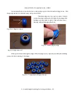
down until it comes into contact with the depth stop (green arrow in Fig. 7.2-2) that you installed in the
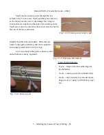
tower assembly. After the tower is set, use a 5/32 Allen (hex) wrench to slightly tighten the ¼-20 cap
screws (finger tight). You'll tighten them up after the top as been mounted.
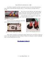
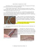
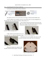
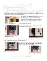
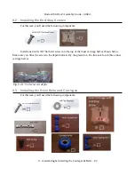
While the Z and X tower wires exit to the right, the Y
tower wiring exits to the left as you can see in Fig. 7.2-4.
Fig. 7.2-3 reflects the use of the older (4 conductor, 18ga) wire, but the path remains the
same for the new 18/26ga wire pairs.
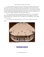
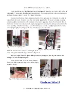
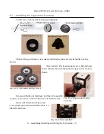
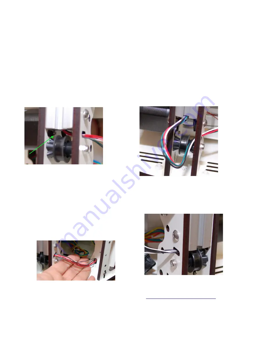
Now you can route the Z axis wiring forward
through the hole on the right edge of the power supply
mount as shown.
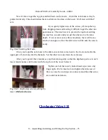
Checkpoint Video #9
7 – Installing the Towers & Tower Wiring – 67
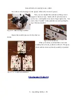
Fig. 7.2-2: Z Tower fully seated.
Fig. 7.2-3: Setting the X tower.
(Old)
Fig. 7.2-4: Y tower wiring.
Fig. 7.2-5: Z Axis wiring routed forward.


