


Rostock MAX v2 Assembly Guide – 4thEd.
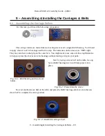
8.3 – Installing the End Stop Switches
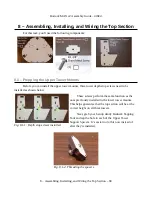
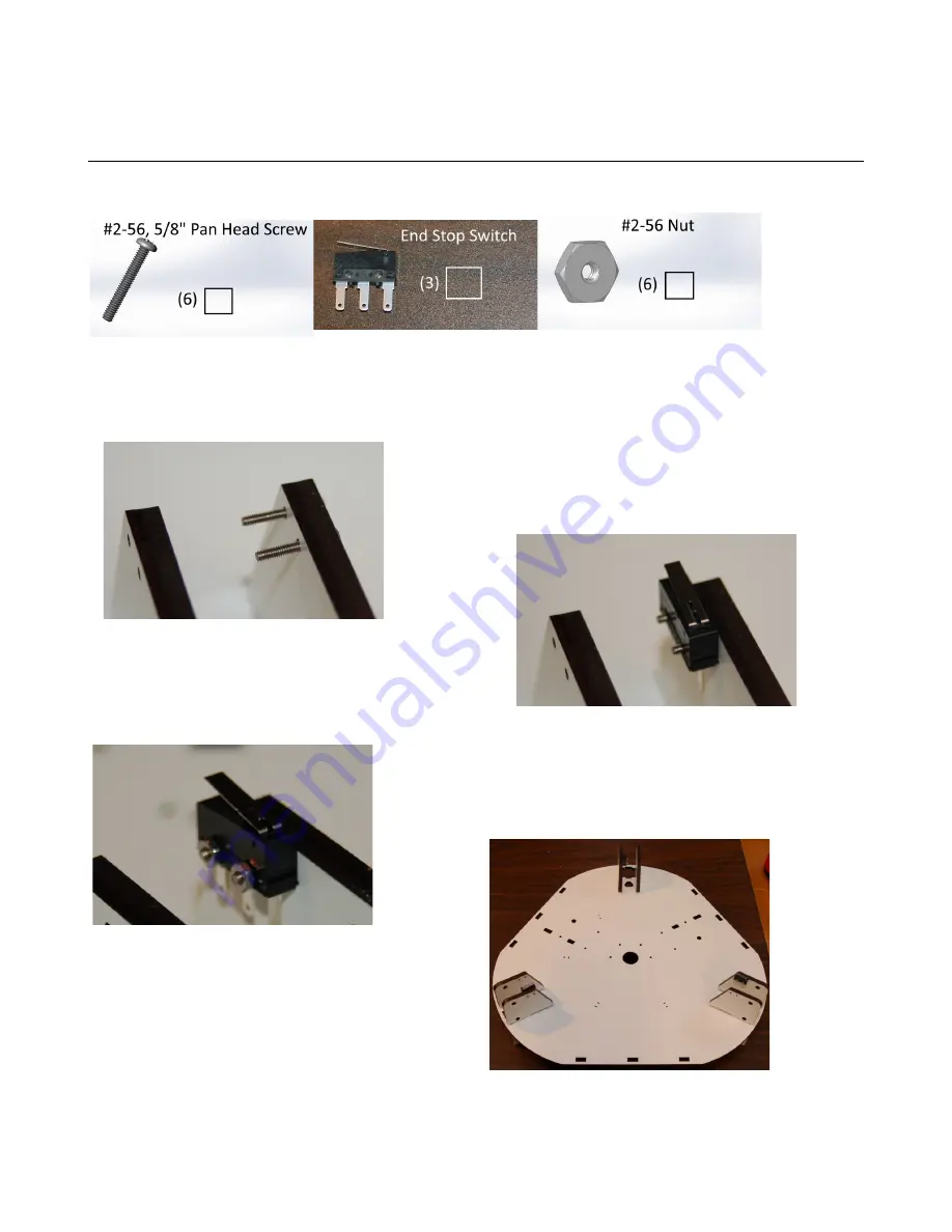
For this task, you'll need the following components:
The end stop switches can be found in the zip lock baggie included with the RAMBo board.
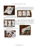
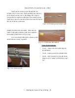
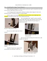
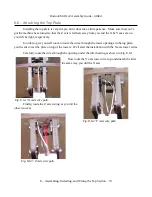
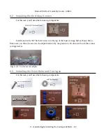
Start the installation by inserting two #2-56, 5/8” pan head screws into the mounting holes on
the right side of the over-turned tower mount as shown in Fig. 7-12.
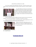
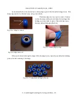
Next, you'll slide the end stop switch over the two screws.
Make sure you've got the switch properly oriented. The back
of the switch should be closest to you as shown.
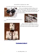
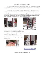
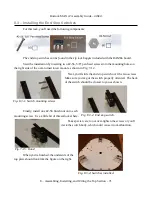
Finally, install one #2-56 finish nut on to each
mounting screw. Use a little bit of thread-locker here.
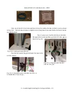
Take special care to not over-tighten the screws or you'll
crack the switch body, which could cause it to malfunction.
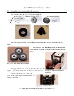
When you're finished, the underside of the
top plate should look like the figure on the right.
8 – Assembling, Installing, and Wiring the Top Section – 71
Fig. 8.3-1: Switch mounting screws.
Fig. 8.3-2: End stop switch.
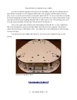
Fig. 7-15: Done!
Fig. 8.3-4: Switches installed.


