


Rostock MAX v2 Assembly Guide
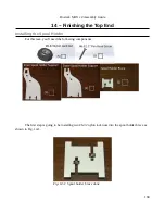
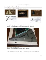
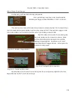
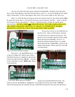
screws at the locations shown below. Do not tighten the screws all the way – leave them a few turns
loose.
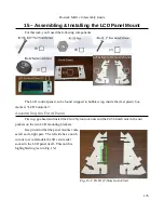
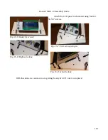
Next, install two more of the #2-56, 5/8” screws at the top front of the faceplate and tighten.
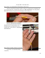
Tighten the lower screws at this time. Install the knob last.
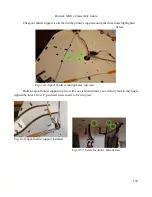
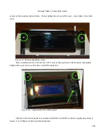
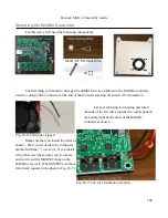
Flip the LCD control panel over and mark the EXP1 and EXP2 connector positions as shown
below. Use a Sharpie or other permanent marker.
180
Fig. 15-11: Bottom faceplate screws.
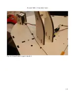
Fig. 15-12: Completed LCD control panel.
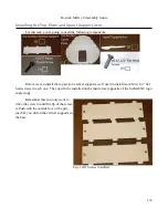
Summary of Contents for Rostock MAX v2
Page 25: ...Rostock MAX v2 Assembly Guide Melamine Parts Sheet 1 25 ...
Page 26: ...Rostock MAX v2 Assembly Guide Melamine Parts Sheet 2 Melamine Parts Sheet 3 26 ...
Page 27: ...Rostock MAX v2 Assembly Guide Melamine Parts Sheet 4 27 ...
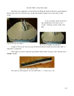
Page 171: ...Rostock MAX v2 Assembly Guide 171 Fig 14 8 Spool holder support installed ...


