


Rostock MAX v2 Assembly Guide
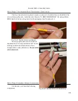
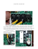
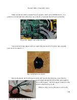
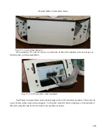
Hold or tape the wires into place and flip the RAMBo controller upside down so you can reach
the solder pads on the back side of the board. Solder the leads in place.
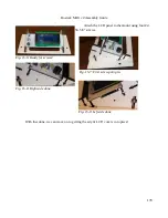
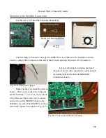
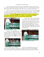
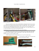
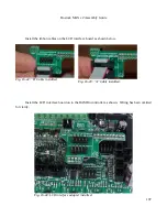
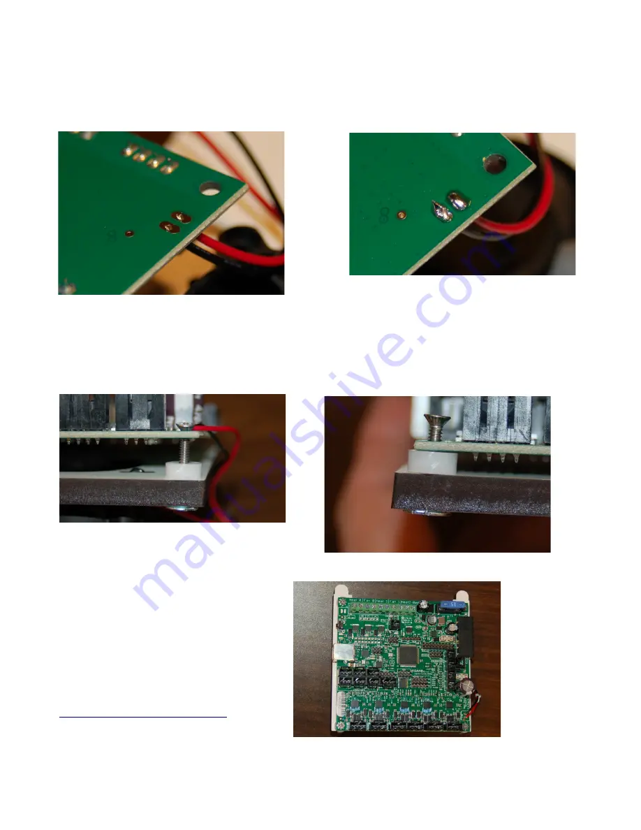
Mounting the RAMBo is very straightforward. Simply set the RAMBo on top of the mount and
slide a plastic roller between the RAMBo and the mounting plate as shown in Fig. 16-10. Insert a #4-
40, 3/4” flat head screw in the hole and tighten a few turns.
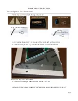
When you've got all four screws
started, go ahead and tighten them all down.
Take care to not over tighten them or you'll
damage the circuit board!
Checkpoint Video #20:
185
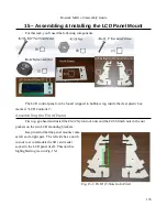
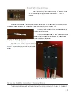
Fig. 16-8: Fan power solder pads.
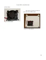
Fig. 16-9: All done.
Fig. 16-10: Starting the screw.
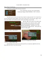
Fig. 16-11: Same idea, different screw.
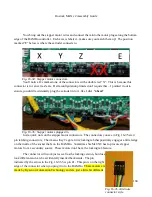
Fig. 16-12: Done!
Summary of Contents for Rostock MAX v2
Page 25: ...Rostock MAX v2 Assembly Guide Melamine Parts Sheet 1 25 ...
Page 26: ...Rostock MAX v2 Assembly Guide Melamine Parts Sheet 2 Melamine Parts Sheet 3 26 ...
Page 27: ...Rostock MAX v2 Assembly Guide Melamine Parts Sheet 4 27 ...
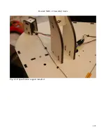
Page 171: ...Rostock MAX v2 Assembly Guide 171 Fig 14 8 Spool holder support installed ...


