


Rostock MAX v2 Assembly Guide
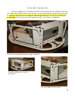
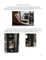
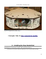
Now let's get the three tower support & motor assemblies attached to the base of the machine.
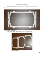
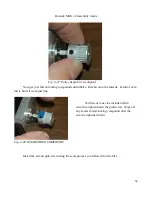
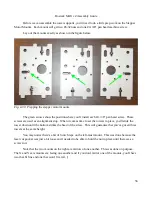
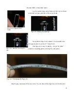
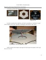
Drop the X and Y axes in as shown below. Install two #6-32, 1” pan head screws into each one,
just a bit more than finger tight. We want a bit of wobble to help with the installation of the top.
60
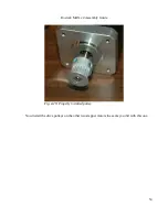
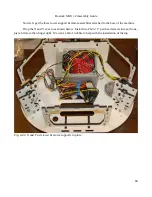
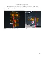
Fig. 4-42: X and Y axis tower & motor supports in place.
Summary of Contents for Rostock MAX v2
Page 25: ...Rostock MAX v2 Assembly Guide Melamine Parts Sheet 1 25 ...
Page 26: ...Rostock MAX v2 Assembly Guide Melamine Parts Sheet 2 Melamine Parts Sheet 3 26 ...
Page 27: ...Rostock MAX v2 Assembly Guide Melamine Parts Sheet 4 27 ...
Page 171: ...Rostock MAX v2 Assembly Guide 171 Fig 14 8 Spool holder support installed ...