background image

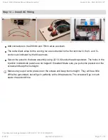
Step 15 — Base Assembly Complete

Congrats! The base assembly is
now complete. We will focus on the
top assembly next.

Step 16 — Wrap-Up

This Sub-Assembly can be set aside until Step 4. Rostock Max v3 Final Assembly.

Proceed to: 

Step 3. Rostock Max v3 Top Assembly

Step 2. REV2 Rostock Max v3 Base Assembly

Draft: 2018-07-27

Guide ID: 66 -

This document was generated on 2019-10-01 12:14:14 AM (MST).

© 2019

seemecnc.dozuki.com/

Page 12 of 12

Summary of Contents for Rostock Max v3

Page 1: ...e Written By SeeMeCNC INTRODUCTION This assembly guide will walk you though the steps of assembly the base of the Rostock Max v3 printer Step 2 REV2 Rostock Max v3 Base Assembly Draft 2018 07 27 Guide ID 66 This document was generated on 2019 10 01 12 14 14 AM MST 2019 seemecnc dozuki com Page 1 of 12 ...

Page 2: ...king from both sides of all laser cut panels This masking helps protect the components during the cutting packing shipping process Step 2 REV2 Rostock Max v3 Base Assembly Draft 2018 07 27 Guide ID 66 This document was generated on 2019 10 01 12 14 14 AM MST 2019 seemecnc dozuki com Page 2 of 12 ...

Page 3: ...ket Needle nose pliers make this a breeze Only thread the t slot nuts on a few threads you need to leave room for the tower channel to slide between the t slot nut and the face of the injection molded mount The threads on the blind nuts have a flange on one side The flanged side should be away from the head of the screw Step 2 REV2 Rostock Max v3 Base Assembly Draft 2018 07 27 Guide ID 66 This doc...

Page 4: ...emember to only get the nut started on the screw Press the bearing cover assembly pre assembled by SeeMeCNC onto the posts inline with the 1 4 20 hardware position shown The two halves will be fastened together with 4 x 1 2 screws Complete 3 identical assemblies Step 2 REV2 Rostock Max v3 Base Assembly Draft 2018 07 27 Guide ID 66 This document was generated on 2019 10 01 12 14 14 AM MST 2019 seem...

Page 5: ...iew This animation will provide you with an overview of what will be assembled Step 2 REV2 Rostock Max v3 Base Assembly Draft 2018 07 27 Guide ID 66 This document was generated on 2019 10 01 12 14 14 AM MST 2019 seemecnc dozuki com Page 5 of 12 ...

Page 6: ... tighten as shown Blue bed clamps should rotate very easily but not be loose You will be installing 6 bed clamps and support blocks around the periphery of the hole in the center of the laser cut plate Step 2 REV2 Rostock Max v3 Base Assembly Draft 2018 07 27 Guide ID 66 This document was generated on 2019 10 01 12 14 14 AM MST 2019 seemecnc dozuki com Page 6 of 12 ...

Page 7: ... hardware pack 84493 If you are located in the US make sure the 220 110 switch is in the 110 115 position as indicated by the arrow This defines the input voltage the power supply expects If you re in a country where 220v is the standard make sure the switch is on the 220 setting Step 2 REV2 Rostock Max v3 Base Assembly Draft 2018 07 27 Guide ID 66 This document was generated on 2019 10 01 12 14 1...

Page 8: ...ly damaged if you over tightne You may wish to leave the soft rubber feet off until you ve completed the assembly of your Rostock MAX v3 The soft feet have a strong grip to them and can make turning the printer difficult Step 2 REV2 Rostock Max v3 Base Assembly Draft 2018 07 27 Guide ID 66 This document was generated on 2019 10 01 12 14 14 AM MST 2019 seemecnc dozuki com Page 8 of 12 ...

Page 9: ... low point of the rocker is closest to the terminal near the edge of the switch The power supply cooling fan has both rotation and airflow direction marks on the side of the fan Make sure that the airflow direction arrow points towards the panel Don t forget to apply the safety warning sticker Step 2 REV2 Rostock Max v3 Base Assembly Draft 2018 07 27 Guide ID 66 This document was generated on 2019...

Page 10: ...l provide you with an overview of what will be assembled Assemble all components sub assemblies to the base plate first Then install the top plate All fasteners used are 6 32 x 1 Step 2 REV2 Rostock Max v3 Base Assembly Draft 2018 07 27 Guide ID 66 This document was generated on 2019 10 01 12 14 14 AM MST 2019 seemecnc dozuki com Page 10 of 12 ...

Page 11: ... injection molded side panels are not tapped threaded Make sure you put some pressure on the screws and keep them straight Make sure you put some pressure on the screws and keep them straight They will be a little difficult to get started but will go in perfectly with a little pressure The screws will go in much easier the second time Step 2 REV2 Rostock Max v3 Base Assembly Draft 2018 07 27 Guide...

Page 12: ...ext Step 16 Wrap Up This Sub Assembly can be set aside until Step 4 Rostock Max v3 Final Assembly Proceed to Step 3 Rostock Max v3 Top Assembly Step 2 REV2 Rostock Max v3 Base Assembly Draft 2018 07 27 Guide ID 66 This document was generated on 2019 10 01 12 14 14 AM MST 2019 seemecnc dozuki com Page 12 of 12 ...

Reviews: