background image

6. EXTRACTOR HOOD INSTALLATION INSTRUCTIONS 


6.1 

This model of the cooker hood is installed (mounted) on the bottom of the kitchen closet.


6.2

 Remove a cooker hood from the packing box. 

6.3

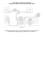
 Check the work of the cooker hood, connect to the electric mains and check all its functions. 

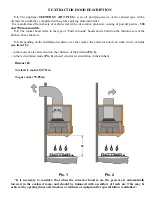
We  remind  that  the  height  of  installation  of  a  cooker  hood  over  the  electric  cookers  should  be  at  least 

650mm, and above the gas one – not less than 750mm (Pic. 1). 


6.4

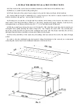
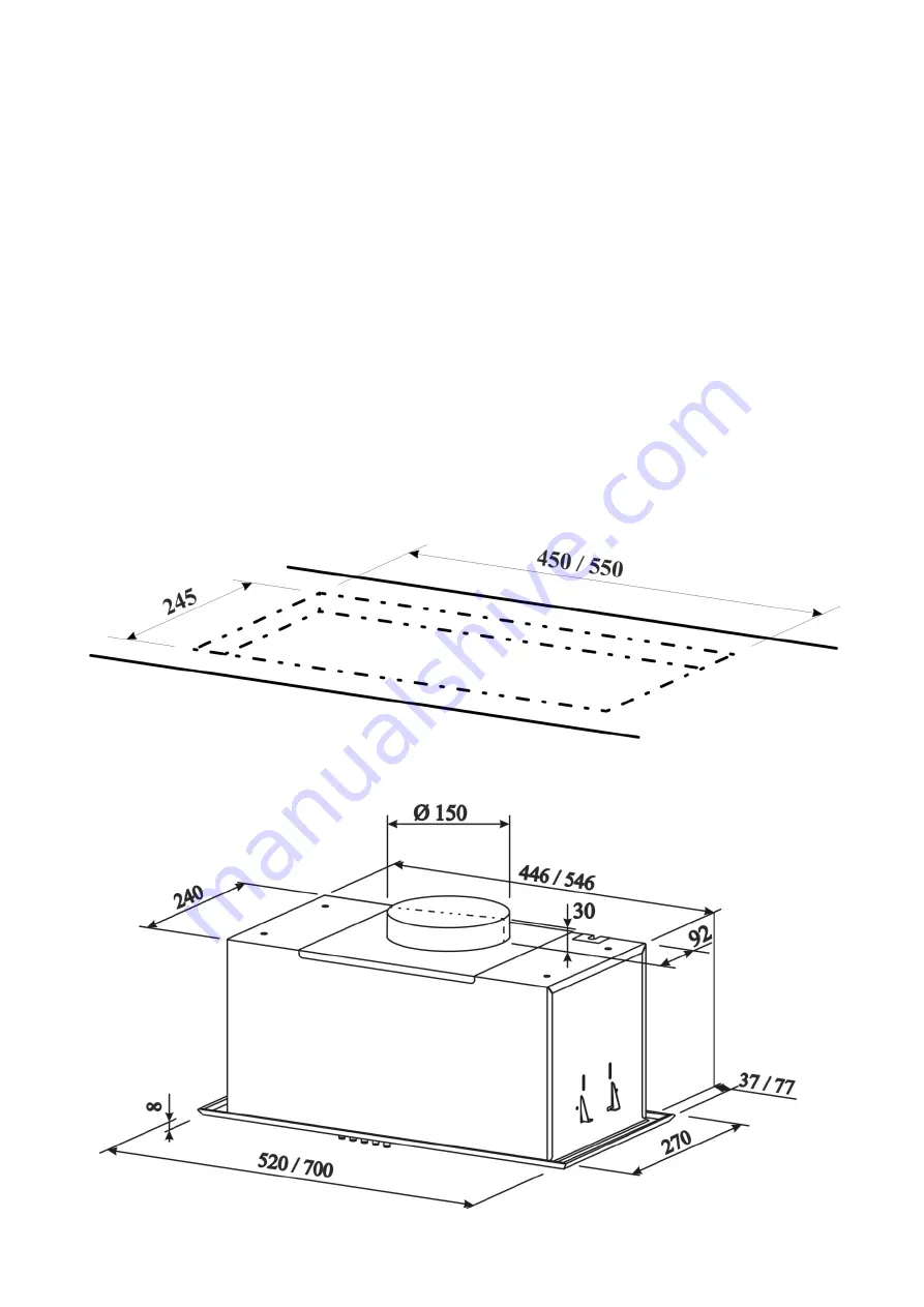
  Taking  into  account  the  set  height  and  the  condition  of  the  fitting  of  the  hood  to  the  bottom  of  the 

lower  shelf  of  the  hinged  furniture  cabinet  in  a  previously  manufactured  paper  template,  mold  and  cut  a 
rectangular hole in accordance with the size (Pic. 3 / 3.1) of the built-in part of the hood. 

6.5

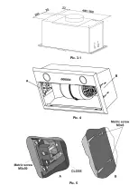
 On the cooker hood, release the screw at 0.5 turns (Pic. 5B). After that, insert the extractor into the cut 

rectangular hole, lightly pressing the elastic clamps (Pic.. 5A). Tighten the screws (Pic. 5A) on both sides. 
Insert the second end of the air duct into the ventilation hole in the wall. The shorter and faster the air flow, 
the higher the performance and the less noise and vibration in the hoods. 
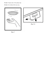
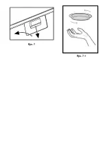
6.6

  Check  the  reliability  of  the  cooker  hood  mounting,  feed  and  connect  the  cord  to  the  mains  through 

socket. 

In  order  to  provide  additional  protection  against  voltage  fluctuations  in  the  network,  we  recommend 

connecting the cooker hood via an additional automatic circuit switch 6A. 


Pic. 3 

Summary of Contents for HIT PLUS

Page 1: ...KITCHEN EXTRACTOR HOOD OKAP KUCHENNY WENTYLACYJNY HIT PLUS USER S MANUAL INSTRUKCJA OBSŁUGI ...

Page 2: ...sheets of carbon steel with a decorative protective coating of powder paints 520 mm and 700 mm in width 1 5 Depending on the installation scheme over the cooker the extractor hood can work in two variants in the mode of air extraction into the stationary ventilation shaft chimney of the kitchen using corrugated aluminum or plastic air ducts Ø150mm or Ø120mm see item 5 3 in the recirculation mode c...

Page 3: ...requency Hz 50 Control type mechanic Number of operation modes 3 Rated power consumption W Of the motor 200 Lighting LED 2x3 General 206 Productivity while connecting to standard ventilation system m3 hour Overall dimensions of the extractor hood mm Width 520 700 Depth 270 Height 217 Connection size of ventilation duct mm Ø150 Ø120 Weight kg 5 3 520mm 5 6 700mm Noise level dB 69 1 520mm 66 0 700mm...

Page 4: ... hood must be plugged into a grounded outlet 4 3 The extractor hood connected to the separate ventilation shaft It is forbidden to connect other appliances to the same ventilation shaft 4 4 Using the extractor hood together with other heating appliances gas oil ovens etc besides electric it is necessary to provide the premises it which the extractor hood is installed with the additional flow of th...

Page 5: ... above the stove 5 3 Depending on the installation scheme over the cooker the extractor hood can work in two variants see item 1 5 in the mode of air extraction into the chimney of the kitchen Pic 1 in the recirculation mode Pic 2 closed circular air circulation in the kitchen It is necessary to consider that when the extractor hood is on the pressure is automatically lowered in the enclosed room ...

Page 6: ...ufactured paper template mold and cut a rectangular hole in accordance with the size Pic 3 3 1 of the built in part of the hood 6 5 On the cooker hood release the screw at 0 5 turns Pic 5B After that insert the extractor into the cut rectangular hole lightly pressing the elastic clamps Pic 5A Tighten the screws Pic 5A on both sides Insert the second end of the air duct into the ventilation hole in...

Page 7: ...Pic 3 1 Pic 4 Pic 5 ...

Page 8: ...7 When cleaning avoid getting moisture on the current carrying parts of the extractor hood and wipe the surfaces with a soft cloth after washing 7 8 The aluminum filter holding oil and dust from the air is clogged and should be washed after being soaked in hot water with an effective detergent once every 1 5 to 2 months Changing the color of the filter after washing does not affect the quality of ...

Page 9: ...Picture 7 Replacement of the lighting lamp Picture 7 1 Aluminum filter removing Pic 7 1 Pic 7 ...

Page 10: ...em węglowym pochłaniającym zapachy Produkt jest produkowany o szerokości 500 600 lub 900 mm z blachy ze stali węglowej z dekoracyjno ochronną powłoką farbami proszkowymi 1 5 W zależności od schematu instalacji nad kuchenką okap może pracować w dwóch wariantach w trybie odprowadzania powietrza w stacjonarny szyb wentylacyjny komin kuchenki z wykorzystaniem falistych aluminiowych lub plastikowych pr...

Page 11: ...J ZARZĄDZANIA MECHANIKA ILOŚĆ TRYBÓW PRACY 3 MOC ZNAMIONOWA W SILNIKA ELEKTRYCZNEGO 200 LAMP OŚWIETLENIA 2x3 LED OGÓLNE 206 WYDAJNOŚĆ PO PODŁĄCZENIU DO STANDARDOWEGO SYSTEMU WENTYLACYJNEGO M Godz WYMIARY OKAPU MM SZEROKOŚĆ 520 700 GŁĘBOKOŚĆ 270 WYSOKOŚĆ 217 PODŁĄCZENIOWY ROZMIAR PRZEWODU POWIETRZNEGO WENTYLACYJNEGO MM Ø150 Ø120 MASA KG 5 3 520mm 5 6 700mm POZIOM HAŁASU DB 69 1 520mm 66 0 700mm KLA...

Page 12: ... w pomieszczeniu w którym jest zainstalowany okap dodatkowy dopływ świeżego powietrza np otworzyć okno 4 5 Podczas montażu okapu na niezbędnej wysokości montażowej N nad kuchenką rys 1 do odprowadzenia powietrza w kominie należy użyć przewodu powietrznego Ø150 Ø120 mm Mniejsza średnica stworzy dodatkowy opór powietrzu co spowoduje wzrost hałasu i wibracji a także do przegrzania silnika 4 6 Zapewni...

Page 13: ...okapu podłączyć go do sieci elektrycznej i sprawdzić wszystkie jego funkcje Przypominamy że wysokość zabudowy okapu nad kuchenką elektryczną powinna być co najmniej 650 mm a nad gazową najmniej 750 mm Rys 1 6 4 Biorąc pod uwagę wysokość i dopasowanie okapu do dolnej części dolnej półki szafki meblowej we wcześniej wykonanym szablonie papierowym uformuj i wytnij prostokątny otwór zgodnie z rozmiare...

Page 14: ...trza tym wyższa wydajność oraz mniej hałasu i wibracji w okapach 6 6 Sprawdź dokręcenie mocowania okapu przesuń i podłącz przez gniazdko przewód zasilający do sieci elektroenergetycznej W celu dodatkowej ochrony przed przepięciami w sieci należy podłączyć okap przez dodatkowy bezpiecznik 6A Rys 3 Rys 3 1 ...

Page 15: ...iom wentylacji 7 2 Przed rozpoczęciem gotowania przełącz okap w odpowiedni tryb pracy Zaleca się kontynuować pracę okapu 3 5 minut po zakończeniu gotowania w ten sposób powietrze w kuchni będzie oczyszczone z pozostałości oparów i zapachów 7 3 Na dolnej płaszczyźnie obudowy umieszczony przełącznik przyciskowy trybów pracy i włączenia lamp oświetlenia Rys 6 Rys 4 Rys 5 ...

Page 16: ... kurz z powietrza filtr aluminiowy zapycha się i należy go umyć po moczeniu w gorącej wodzie z efektywnym środkiem do zmywania 1 raz na 1 5 2 miesiące Zmiana koloru filtra po umyciu nie wpływa na jakość jego pracy 7 10 Do zdejmowania filtra aluminiowego Rys 7 należy kliknąć na zatrzask sprężynowy i ciągnąc do siebie i w dół zdjąć filtr z panelu Montaż filtra wykonać w odwrotnej kolejności Nie inst...

Page 17: ...Rys 7 1 Rys 7 ...

Page 18: ...TIC DIAGRAM ZASADNICZY SCHEMAT INSTALACJI ELEKTRYCZNEJ OKAPU Electrical schematic diagram of the sensor extractor hood HIT PLUS with capacity 520 700 mm Schemat elektryczny okapu wyciągowego czujnika HIT PLUS 520 700 mm ...

Page 19: ...heck the socket For the power connection Sprawdź gniazdo czy jest w nim napięcie Check lamps Sprawdź lampy Check air outlet pipe for the traction Sprawdź rurę wylotową powietrza powinien być wyciąg Check carbon filter replacement once every 3 4 months Sprawdź filtr węglowy wymiana 1 raz w 3 4 miesiące Extractor hood does not work Okap nie działa The lamp does not light Nie świeci lampa Reduced per...

Reviews: