background image

Page 2.1

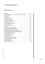
2.0 Safety Instructions

Safety Instructions for 548.04 \ 05.2010 \

Table of contents

General. . . . . . . . . . . . . . . . . . . . . . . . . . . . . . . . . . . . . . . . . . . . 2.3
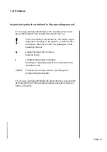
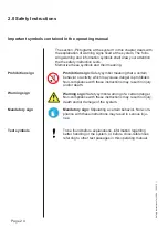
Important symbols contained in the operating manual. . . . . . . . 2.4
Prohibition sign. . . . . . . . . . . . . . . . . . . . . . . . . . . . . . . . . . . . . . 2.4
De

fi

 nitions. . . . . . . . . . . . . . . . . . . . . . . . . . . . . . . . . . . . . . . . . . 2.5

Remaining risks  . . . . . . . . . . . . . . . . . . . . . . . . . . . . . . . . . . . . . 2.5
Operating personnel   . . . . . . . . . . . . . . . . . . . . . . . . . . . . . . . . . 2.5
Protective clothing  . . . . . . . . . . . . . . . . . . . . . . . . . . . . . . . . . . . 2.5
Accident Prevention Rules   . . . . . . . . . . . . . . . . . . . . . . . . . . . . 2.6
Operation of system . . . . . . . . . . . . . . . . . . . . . . . . . . . . . . . . . . 2.7
General safety instructions. . . . . . . . . . . . . . . . . . . . . . . . . . . . . 2.7
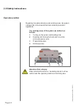
Operator position  . . . . . . . . . . . . . . . . . . . . . . . . . . . . . . . . . . . . 2.8
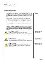
Symbols at the system . . . . . . . . . . . . . . . . . . . . . . . . . . . . . . . . 2.9
General. . . . . . . . . . . . . . . . . . . . . . . . . . . . . . . . . . . . . . . . . . . . 2.9
Warning sign for high voltage . . . . . . . . . . . . . . . . . . . . . . . . . . . 2.9
Warning sign for danger of burns . . . . . . . . . . . . . . . . . . . . . . . . 2.9
Warning sign for accident hazard . . . . . . . . . . . . . . . . . . . . . . . . 2.9
Mounting, dismounting, and maintenance . . . . . . . . . . . . . . . . . 2.10
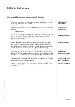
You should know and observe the following. . . . . . . . . . . . . . . . 2.11
EMERGENCY SHUT-OFF . . . . . . . . . . . . . . . . . . . . . . . . . . . . . 2.11
Acoustically indications. . . . . . . . . . . . . . . . . . . . . . . . . . . . . . . . 2.11
Danger of burns  . . . . . . . . . . . . . . . . . . . . . . . . . . . . . . . . . . . . . 2.11
Accident hazard  . . . . . . . . . . . . . . . . . . . . . . . . . . . . . . . . . . . . . 2.11
Hazardous soldering vapors. . . . . . . . . . . . . . . . . . . . . . . . . . . . 2.11
Instructions from other suppliers  . . . . . . . . . . . . . . . . . . . . . . . . 2.11
EMC instructions  . . . . . . . . . . . . . . . . . . . . . . . . . . . . . . . . . . . . 2.11
Disposal instructions. . . . . . . . . . . . . . . . . . . . . . . . . . . . . . . . . . 2.12
General remarks. . . . . . . . . . . . . . . . . . . . . . . . . . . . . . . . . . . . . 2.12

Summary of Contents for 548.04

Page 1: ...nal manual Change or modifications with corresponding publications Published by the manufacturer SEF Roboter GmbH Kringelsburg 21379 Scharnebeck GERMANY Telefon 49 0 4136 909 0 Telefax 49 0 4136 909 22 Operating Manual IR Force Convection Soldering System 548 04 System Settings Maintenance Measurement Production Operating the System Prior to Operation Quick Reference Guide Safety Instructions Pref...

Page 2: ... SEF Roboter GmbH Version 1 0 03 2010 Translation of original manual Change or modifications with corresponding publications ...

Page 3: ...g manual 1 9 Technical Data 1 10 Emmissions 1 10 Sound compression 1 10 2 0 Safety Instructions General 2 3 Important symbols contained in the operating manual 2 4 Prohibition sign 2 4 Warning sign 2 4 Mandatory sign 2 4 Text symbols 2 4 Definitions 2 5 Remaining risks 2 5 Operating personnel 2 5 Protective clothing 2 5 Accident Prevention Rules 2 6 Operation of system 2 7 General safety instructi...

Page 4: ...Connection 3 4 Mains Switch 3 5 Interface 3 5 Final checkup 3 6 Turn the System on and off 3 7 Turn the System on 3 7 The System Screen 3 7 Enter new Process Parameters 3 8 Create a Soldering or Gluing Profile 3 8 Enter the Temperature Value 3 8 Enter the IR value 3 9 Enter the Speed 3 9 Turn the heaters on and off 3 9 Save a Program 3 10 Load a Program 3 11 Delete a Program 3 11 Program Printout ...

Page 5: ...of delivery 4 4 Connecting the System 4 5 Dimensions of theSoldering System 4 6 Connections at the System 4 7 Electrical Connection 4 7 Exhaust Air Connection 4 8 Mount the slip 4 9 Extension for the cooling zone 4 9 Use as a slip 4 9 Interface 4 10 Printer Interface 4 10 Mains Switch 4 10 Final checkup 4 11 Dismounting the system 4 12 Preservation and storage of the system 4 13 System preparation...

Page 6: ...or Gluing Profile 5 12 Enter the Values 5 13 Confirm 5 13 Abort 5 13 Enter the Speed 5 14 Abort 5 14 Confirm 5 14 Parameter Printout 5 15 Parameter Printout 5 15 Select a Place 5 17 Overwrite a Program 5 17 Identification 5 17 Program Printout 5 20 6 0 Production Start the Production 6 3 Turn the System on 6 3 Load a Program 6 4 Program Selection 6 4 Process Documentation 6 5 Parameter Printout 6 ...

Page 7: ...out 8 4 Immediate Printout 8 4 Enter Interval time 8 5 Select Contrast 8 6 Select contrast 8 6 Select Printer Type 8 7 Select printer 8 7 System Service 8 8 9 0 Maintenance Cleaning intervals 9 3 Cleaning 9 3 Relieved cleaning work 9 4 Cleanings with water and washing up liquide or spirit 9 4 Open covers 9 5 Close covers 9 5 Plan of Diagnosis 9 6 The Electronic of the Soldering System 9 8 Change t...

Page 8: ...easurement System 11 3 MESY 570 70 Measurement System 11 3 MESY 570 77 Insulating box 11 3 MESY 570 80 Profiler Set 11 3 Thermocouple sensor 11 3 Conveyor extension TFV 200 11 4 Dimensions of the conveyor extension TFV 200 11 4 Dimenstions of the soldering system 548 04 with conveyor extension TFV 200 11 4 Functional description 11 5 Intended use 11 5 Conformity according to EC machinery directive...

Page 9: ... 5 Conformity according to EC machinery directive 11 5 Connecting the System 4 5 Connections at the System 4 7 Contrast 8 6 Conveyor extension TFV 200 11 4 Create a Soldering or Gluing Profile 3 8 5 12 D Danger of burns 2 11 Defect Radiator 9 9 Definitions 2 5 Delete a Program 3 11 5 19 Dimensions of theSoldering System 4 6 Dimensions of the conveyor extension TFV 200 11 4 Dimenstions of the solde...

Page 10: ...ting 3 19 Interval time 8 5 Introduction 1 3 L Language Selection 3 17 8 3 LCD 5 5 Liability 1 6 Load a Process Curve 3 14 7 5 Load a Program 3 11 5 18 6 4 M Mains Filter 9 26 10 6 Mains Switch 3 5 4 10 5 5 Mandatory sign 2 4 Manual 1 7 Measurement Screen 5 8 Measurement System 11 3 MESY 570 70 11 3 MESY 570 77 11 3 MESY 570 70 11 3 MESY 570 77 11 3 MESY 570 80 11 3 Menu Structure 5 7 Mounting dis...

Page 11: ...tout 3 12 Program Screen 5 8 Program Selection 5 18 6 4 Prohibition sign 2 4 Proper use 1 4 Protection of the product 1 5 Protective clothing 2 5 Protocol printout 3 19 8 4 Immediate Printout 8 4 R Recording a Process Curve 3 13 7 3 Relieved cleaning work 9 4 Remaining risks 2 5 S Safety instructions 11 9 Save a Process Curve 3 15 7 7 Save a Program 3 10 5 16 Screen 5 8 Measurement Screen 5 8 Para...

Page 12: ... off 3 9 Turn the heating system on 6 6 Turn the System off 6 6 Turn the System on 3 7 6 3 Turn the System on and off 3 7 5 9 U Unpacking 3 3 Unpacking and controlling the parts of delivery 4 4 Unpacking the system 4 4 Used norms 11 7 Use as a slip 4 9 Utilization rights 1 5 W Warning sign 2 4 Warning sign for accident hazard 2 9 Warning sign for danger of burns 2 9 Warning sign for high voltage 2...

Page 13: ...f the product 1 5 Warranty 1 5 Warranty claim processing 1 5 Product modifications or improvements 1 6 Particular restrictions 1 6 General provisions 1 6 Assignment of utilization rights 1 6 Liability 1 6 Informations about this operating manual 1 7 Important symbols contained in the operating manual 1 9 Technical Data 1 10 Emmissions 1 10 Sound compression 1 10 ...

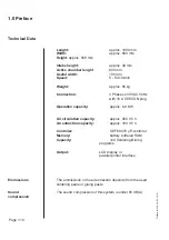
Page 14: ...Page 1 2 1 0 Preface Preface for 548 04 05 2010 ...

Page 15: ...ht be damaged It is absolutely necessary that you read this operating manual prior to transporting mounting or operating the Reflow System Therefore use the Reflow System only in proper condition according to the rules being aware of possible safety problems and hazards and under consideration of all information provided in this operating manual This operating manual contains rules and guidelines ...

Page 16: ... operating and maintenance conditions as predeter mined by us the EMV notes as well as with the dispo sal measures Only qualified authorized and trained persons are allowed to operat at and with the Reflow System Each person conducting the transportation or any work at or with the Reflow System has to have read and understood the appropriate parts of this opera ting manual and especially the chapt...

Page 17: ...ill carry out repairs free of charge within a peri od of 12 months after free return of the product The warranty commences on the day of delivery which must be verified to us with the enclosed warranty cer tificate Within the warranty period we will remedy all product malfunctions which are the result of defective work manship free of charge The warranty does not include consumables and wearing pa...

Page 18: ...is prohibited to copy or otherwise reproduce the product and the written documents either in whole or in part in their original or modified form It is prohibited to modify the product and in particu lar to translate back develop decompile or deas semble the software contained in the product By giving away rental and loan of the product the SEF Roboter GmbH must be informed if not the war ranty exp...

Page 19: ...observe in the system s environment You will also find information on disposal of the system Chapter 3 Quick Reference Guide This chapter is for the well known user Here you will get in a short information how to erect adjust connect programm use and produce with the system Chapter 3 Proir to Operation This chapter informs on general rules for functioning of the system We explain how to erect and ...

Page 20: ... System Settings In this chapter we explain how to change the basic set ting Chapter 9 Maintenance This chapter gives answers for possible problems by the work and mainteance informations of the system Chapter 10 Technical appendix This chapter provides a survey on the system Chapter 11 Accessories All accessories at a glance Chapter 12 Notes This chapter is for your personal notes ...

Page 21: ...er handling or the system or before cross references referring to other text passages in this operating manual Listing following this rhombus General listing Listings following this rectangle Working or operating steps to be conducted in the described order Text These texts are entry texts for operating and programming the system For an easy reading and finding of special themes you will find at t...

Page 22: ...AC 50 Hz with 16 A CEECON plug Operation capacity approx 6 8 KW Air circulation capacity approx 900 m3 h Air extraction capacity approx 180 m3 h Controler SEF 68070 µP controler Memory battery buffered RAM Capacity 120 Soldering Gluing programs Output LCD display or parallel printer interface The emmissions in the air extraction depends from the used soldering paste or gluing paste The sound compr...

Page 23: ...eral safety instructions 2 7 Operator position 2 8 Symbols at the system 2 9 General 2 9 Warning sign for high voltage 2 9 Warning sign for danger of burns 2 9 Warning sign for accident hazard 2 9 Mounting dismounting and maintenance 2 10 You should know and observe the following 2 11 EMERGENCY SHUT OFF 2 11 Acoustically indications 2 11 Danger of burns 2 11 Accident hazard 2 11 Hazardous solderin...

Page 24: ...Page 2 2 2 0 Safety Instructions Safety Instructions for 548 04 05 2010 ...

Page 25: ... and at the system Each person working with this system has to have read and understood the complete operating manual and especially this chapter Safety instructions are for maintenance of industrial health and safety standards as well as for accident prevention Always follow the safety instructions Therefore keep this operating manual near the system easily accessible To protect you and your coll...

Page 26: ...r is prohibited Non compliance with these instructions may result in injury and or death Warning sign Safety symbol warning of a certain danger Non compliance with these instructions may result in injury death and or damage of the system Mandatory sign Stipulating a certain behavior Non com pliance with these instructions may result in serious inju ries To be found before explanations information ...

Page 27: ...formed qualified and trai ned possessing sufficient knowledge due to their education and experience in a special field and are familiar with the cor responding relevant regulations on industrial health and safety standards as well as on accident prevention They are also familiar with the generally recognized technical rules Only such persons are allowed to mount dismount start operation do mainten...

Page 28: ...tions valid in your country Especially follow the safety instructions regarding first aid handling of elec trical equipment soldering methods and handling nitrogen You have to protect yourself and other persons from damage Please note the following instructions safety instructions CENELEC safety instructions IEC safety instructions from the gluing paste and soldering paste manufactor Accident Prev...

Page 29: ...with The operating personnel is responsible that only authorized persons work at and with the system Any attempt to impair the system s safety has to be refrained from All protection and warning equipment has to be tested for proper functioning in regular intervals Prior to turning the sys tem on the operating personnel has to convince themselves that no persons or objects are within the working r...

Page 30: ...ositions and working area Operator position Regarding the safety distances and working areas the system corresponds to the relevant German accident prevention regulations The working areas of the system are defined as follows 1 Turning on the system and feeding zone 2 Opening and closing the hood and for service and maintenance work 3 Programming area 4 Discharge zone 1 2 3 4 ...

Page 31: ...te to a stable and trouble free production The following safety symbols are fixed at the system They are warning signs and have to be followed Familiarize yourself with these symbols and pay attention to the following infor mation Danger High voltage Safety symbol at terminal box and switch box Non observance of this warning can result in injury and or death Danger of burns Safety symbol in the he...

Page 32: ...do not carry any current For that secure the main switch against unauthorized operation for example secure by a special lock After electrical mounting or maintenance work check all EMC securities and the corresponding applied protective measures In general no safety device must be dismounted or put out of action If for certain works the dismounting of safety equipment is necessary for installation...

Page 33: ...cham ber In case your hand gets stuck in the conveying system or if you are working inside the system turn the system off via main switch In case of burns contact a physician immediately Soldering vapors are dangerous to your health Connect your system to an internal exhaust air system or to an airwasher sys tem Never let soldering vapors escape into the production area Follow always the safety an...

Page 34: ...lations Please consult your environmental protection agency for further information on proper disposal of these substances Keep the original packaging for later use e g sen ding it back to the manufacturer Ensure proper disposal of electronic componentries The heating chamber and the transfer system can normally be disposed within the common metal sal vaging Refer your soldering pastes manufacture...

Page 35: ...ldering or Gluing Profile 3 8 Enter new Process Parameters 3 8 Enter the Temperature Value 3 8 Enter the IR value 3 9 Enter the Speed 3 9 Turn the heaters on and off 3 9 Program Printout 3 12 Recording a Process Curve 3 13 Mount the Sensor 3 13 Record a Process Curve 3 13 Load a Process Curve 3 14 Analyze a Process Curve 3 14 Save a Process Curve 3 15 Print a Process Curve 3 16 Language Selection ...

Page 36: ...Page 3 2 3 0 Quick Reference Guide Quick Reference Guide for 548 04 05 2010 ...

Page 37: ...kg Remove the system from the packaging with 4 people Otherwise there is danger of accidents Unpacking the system securely Place the system on a table which has been designed for the right weight Fix the slip in the discharging zone Attention Danger Before switching on the system take care that the elec trically power and fuses are aggreing with the connection values If not there is damage for the...

Page 38: ...e nozzle diameter 60 mm at the rear side of the machine Connect the hose to your internal exhaust air system to this nozzle or Connect the hose to the active exhaust air box to this nozzle Place the active exhaust air box under the soldering system Connect the hose to the nozzle on the rear side of the systems hood Connect the hose of the air exahaust box to your internal exhaust air system Secure...

Page 39: ...e plug while the sys tem is turned off In the chapter 10 0 Technical Ap pendix Pin connection you will find the connection and the protocol of the interface Connect the printer with the interface Secure the plug with the screws The system will be turned on and off via mains switch at the operating panel To turn the system on set the mains switch to ON and to turn the system off set the mains switc...

Page 40: ...f the table the same as the sys tem Did you connect the exhaust air nozzle of the system to your internal exhaust air system and did you check whether this connection is tight Does the power supply correspond to the require ments as stated on the type plate Did you have the electrical connection made by a specialist Do the fuses in your production plant correspond to the system s requirements Afte...

Page 41: ...g 03 4 READY 210 C The System will be central switched on and off with the main switch beside the operating panel Turn the main switch to ON On the LCD Display you will get the system information SEF GmbH Reflow System 548 04 c SEF GmbH 2004 Rev 1 0 The system screen appears The System starts with the last stored program You will reach the submenus with the functions keys dis played in the food li...

Page 42: ...perature Press the function key Temp The cursor jumps to the field of the air temperature You accept the value displayed by pressing Enter Alternately you enter a new value with the and keys Your entry must be between 0 and 250 Confirm you entry with Enter The cursor jumps to the field for the value of the radi ator IR Enter new Process Parameters Create a Soldering or Gluing Profile Enter the Tem...

Page 43: ...ommended speeds for the different process times Process time speed approx 3 min 20 cm min approx 3 5 min 17 cm min approx 4 min 15 cm min approx 4 5 min 13 cm min approx 5 min 12 cm min approx 5 5 min 11 cm min approx 6 min 10 cm min Press the function key Conveyor The cursor jumps to the field of the conveyor speed You accept the displayed value by pressing Enter You can change the speed with and...

Page 44: ... be displayed on the LCD if a program is saved on this place With Enter you overwrite the program on this place With Esc you abort this function You get back to the program screen Enter the name of the program Characters or num bers are possible By every pressing of the next character of the alphabet or number follows and by every pressing of the previous charac ter or number follows Confirm the c...

Page 45: ... and Select the program Confirm the program with Load or abort with Esc You get back to the program screen Any saved program can be deleted if no longer needed Press in the system screen Program for program handling You can scroll the directory with and Select the program Delete the program with Delete Confirm the delete function with Enter or abort with Esc You get back to the program screen Load...

Page 46: ...nterface plug while the system is turned off In the chapter 10 0 Technical Appendix Pin connection you will find the connection and the protocol of the interface Press in the system screen Program for program handling You can scroll the directory with and Select the program For the printout of the program press the function key Print The program will be printed You get back to the program screen A...

Page 47: ... plug on the feeding side of the system Press in system screen the function key Measure for measurement You can record save analyse and print out a process curve After the PCB moved into the heating chamber press Measure to start the recording Attention The transport system moves through the extremely hot heating chamber Do not reach into the heating chamber during operation Use heat proof protect...

Page 48: ...curve with Display The pro cess curve will be displayed Load a Process Curve Abort with Esc You get back to the procress curve menu A recorded process curve can be analyzed The electronic will add a vertical line additionaly to the process curve You can move this vertical line in the recorded procress curve In the Infofield you will get in dependence of the vertical line the temperature and the ti...

Page 49: ...The arrows are marking the place Confirm the place with the function key Save With Enter you overwrite the process curve on this place With Esc you abort this function You get back to the procress curve menu Enter the name of the process curve The name can have a lenght of 8 characters Enter the name of the process curve Characters or numbers are possible By every pressing of the next character of...

Page 50: ...e pin connection of the plug and the interface protocol you will find in the chapter 10 0 Technical Appendix Pin Connection Connect the serial printer on the interface plug on the side of the System Press in system screen the function key Measure for measurement You can select the right process curve with and Press Print The process curve will be printed out You get back to the procress curve menu...

Page 51: ...t in your special language Press in the system screen System for system setting Press the function key Language Select your language Move the arrows with und on the favour lanuage Confirm the language with Enter The screen will be changed automatically You get back to the screen of systems setting Abort with Esc You get back to the screen of systems setting Language Selection Select Language ...

Page 52: ...the system display can be changed By different angles of view it is useful to change the contrast of the display Press in the main screen System for system set ting Press in the system screen Service for service setting Select the contrast with and for the dis play Confirm your entry with Esc You get back in the service menue ...

Page 53: ... system screen System for system setting Press Report for protocol printout Press Print for print now The status of the machi ne will be printed out You get back to the menu for protocol printing Press Interval for set printout time The cursor jumps into the field of the time Enter the interval time Your entry could be between 1 60 minutes Confirm your entry with Enter You get back to the screen o...

Page 54: ...Page 3 20 3 0 Quick Reference Guide Quick Reference Guide for 548 04 05 2010 ...

Page 55: ...of damage 4 4 Checking parts of delivery 4 4 Connecting the System 4 5 Dimensions of the Soldering System 4 6 Connections at the System 4 7 Electrical Connection 4 7 Exhaust Air Connection 4 8 Mount the slip 4 9 Extension for the cooling zone 4 9 Use as a slip 4 9 Interface 4 10 Mains Switch 4 10 Printer Interface 4 10 Final checkup 4 11 Dismounting the system 4 12 Preservation and storage of the ...

Page 56: ...Page 4 2 4 0 Prior to Operation Prior to Operation for 548 04 05 2010 ...

Page 57: ...e note the instructions at the packaging Point to fix a chain or a rope at the packaging Indication of center of gravity of packaging Caution fragile This side up Attention do not use hand hooks Protect from direct sunlight This side up Transport only with this side up arrows point upwards For transportation or service please keep the packaging Transportation instructions at the packaging Transpor...

Page 58: ... protest Contact us and the transportation insurance company immediately Attention danger Do not assemble the system and do not connect it to the power supply if any damages are recognizable Due to the damage there is a danger to your life Make sure the contents correspond to the statements made on the note of delivery If delivery and delivery note do not agree please con tact us immediately Keep ...

Page 59: ...must designed for the weight Attention accident hazard The system weights is approx 65 kg Remove the system from the packaging with 2 people on the desk Take care that the desk is secure and not wobbly The soldering system is delivered ready mounted There is only a short installation and connection work to do All connectors are placed on the rear side of the soldering system Electrical connection ...

Page 60: ...eration Prior to Operation for 548 04 05 2010 Dimensions of the Soldering System All dimensions in millimeter mm approx 250 approx 640 approx 1000 Air discharge nozzle Diameter 60 mm power connector 400 VAC 50 Hz 16 A 3 phases ...

Page 61: ...e has a length of 2 m Attention Danger Before switching on the system take care that the elec trically power and fuses are aggreing with the connection values If not there is damage for the life and system Connect the connection cable with the plug of your internal 16A power supply Electrical Connection Connections at the System ...

Page 62: ... there is a discharge nozzle diameter 60 mm at the rear side of the machine Connect the hose to your internal exhaust air system to this nozzle or Connect the hose to the active exhaust air box to this nozzle Place the active exhaust air box under the soldering system Connect the hose on the nozzle of the active exhaust air box to your internal exhaust air system Secure all hoses with the hose cli...

Page 63: ...s a slip Mount the slip The slip has two different mounting angles Place the slip with the straight side on the both screws at the soldering system Place the slip with the angular side on the both screws at the soldering system Please note that you have a pick up possibility desk for the soldered PCBs at the end of the slip Extension for the cooling zone Use as a slip 1 ...

Page 64: ...is turned off In the chapter 10 0 Technical Appendix Pin connection you will find the connection and the protocol of the interface Connect the parallel cable for a printer with the inter face Secure the plug with the screws The system will be turned on and off via mains switch at the operating panel To turn the system on set the mains switch to ON and to turn the system off set the mains switch to...

Page 65: ...e table the same as the sys tem Did you connect the exhaust air nozzle of the system to your internal exhaust air system and did you check whether this connection is tight Does the power supply correspond to the require ments as stated on the type plate Did you have the electrical connection made by a specialist Do the fuses in your production plant correspond to the system s requirements After ha...

Page 66: ... exhaust air connection of the system Remove the hose from the exhaust air nozzle of the system Remove the the plug from the interface Attention accident hazard The system weights is approx 65 kg Remove the system from the packaging with 2 people Otherwise there is dan ger of accidents Now you can remove the system from the production location For erecting the system at another location please rea...

Page 67: ...llowing Turn the system off with the main switch Clean the system as described in the chapter 9 0 Maintenance If you are not operating the system for a prolonged period please note the following Clean the system as described on chapter 9 0 Maintenance Store the system at a dry and dustfree location No other preservation methods are required for the storage System preparati on for vacation Preservi...

Page 68: ...Page 4 14 4 0 Prior to Operation Prior to Operation for 548 04 05 2010 ...

Page 69: ...een 5 8 Parameter Screen 5 8 Program Screen 5 8 Measurement Screen 5 8 System Service Screen 5 8 Turn the System on and off 5 9 The System Screen 5 9 Information of the System Screen 5 10 Turn the System off 5 10 Heating Process On and Off 5 10 Open the Cover 5 11 Parameter Setting 5 12 Create a Soldering or Gluing Profile 5 12 Enter the Values 5 13 Enter the Speed 5 14 Parameter Printout 5 15 Sel...

Page 70: ...5 0 Operation of System Page 5 2 Operation of System for 548 04 05 2010 ...

Page 71: ...played on a LCD The integrated measuring system In case of emergency the system can be shut off completely with the main switch If the systems cover will be opend during th eoperation an acoustical signal sounds the heaters and the blower will be shut off The complete system control is arranged on the rear side of the system The integrated changing of the power input allowes an easy changing to a ...

Page 72: ...R radiator the air is stuck up from the blower The air is heated up on the programmed temperature through the heating elements The hot air is given over the nozzle in the peak zone back into the heating chamber The straighten air circulation is against the transport direction With this a gently warming up of the PCB is given The regulation of the conveyor speed will be done depending on a variance...

Page 73: ...ion block On the operating panel you will find the LCD Display for the graphically displaying the programming and the system para meters Function keys and cursor keys are for the input of the parameters The system is switched on and off with the mains switch next the operating panel The LCD displays the programs and indicates system parame ters both graphically It guides the user with menus Mains ...

Page 74: ...pon the menu being used The actual functions are displayed in the LCD For storing a program or a process curve with the function keys cha racters or a numbers are possible With the and the changing between a character or a number is made Confirm entries and functions with Enter They will then be accepted respectively executed With the key Esc you generally abort a function prior to its execution I...

Page 75: ...tential without making operation unnecessarily difficult this display field is subdivided into various informative pages The differents between the information pages are The system screens which shows informations about the status of the machine The menu screens in which you can operate the machine The calling of the single system and menu screens happens with the function keys only An information...

Page 76: ...0 03 04 05 System Screen Parameter Screen Program Screen Measurement Screen System Service Screen Temp Conveyer Print SETTINGS Air temp 220 IR 4 Conveyer 15 cm min Settings Program Measuring System HEATER 1 V 20 cm min Prg 03 4 READY 210 C Language Report Printer Service SYSTEM SETTINGS Language English Contrast Operating Hour 11 50 32 Protocoll printout 1min Contrast Printer type Epson ...

Page 77: ... switch beside the operating panel Turn the main switch to ON On the LCD Display you will get the system information SEF GmbH Reflow System 548 04 c SEF GmbH 20047 Rev 1 0 The system screen appears The System starts with the last stored program Turn the System on On The System Screen Settings Program Measuring System HEATER 1 V 20 cm min Prg 03 4 READY 210 C ...

Page 78: ...tem off Value of the System status Temperature in IR Radiator the peak zone Status of Conveyer Food line Program Heaters speed number Information of the System Screen You will reach the submenus with the functions keys dis played in the food line With the Enter key you turn on and off the heating process The status is shown in the display Turn the entired System off with the Mains switch ...

Page 79: ... the delivered square wrench Attention danger of burns During the production process the heating chamber is very hot due up to 525 C 980 F In case of burns contact a physician immediately Attention danger of burns Before you remove a circuit board from inside the system make sure you wear heat resistant gloves The circuit board may be very hot and cause burns Open the Cover ...

Page 80: ...in the menu for the settings Press Settings for parameter setting in the system screen The following screen appears Since the program last used is stored in the battery buffe red RAM there will always be values displayed for all for temperature Parameter Setting Create a Soldering or Gluing Profile Temp Conveyer Print SETTINGS Air temp 220 IR 4 Conveyer 15 cm min Settings Program Measuring System ...

Page 81: ...h Enter The cursor jumps to the field for the value of the radi ator IR Enter a new value with the and keys Your entry must be between 0 and 5 0 Radiator turned off 1 5 different values Confirm you entry with Enter You get back to the screen for setting parameters Abort with Esc All made entries are lost You get back to the screen for setting parameters You can change the temperatures of the air t...

Page 82: ...n approx 5 5 min 11 cm min approx 6 min 10 cm min Enter the Speed Press the function key Conveyor The cursor jumps to the field of the conveyor speed You accept the value displayed by pressing Enter Alternately you enter a new value with the and keys Your entry must be between 5 and 60 Confirm you entry with Enter You get back to the screen for setting parameters Abort with Esc All made entries ar...

Page 83: ...ng the interface plug while the system is turned off In the chapter 10 0 Technical Appendix Pin connection you will find the connection and the protocol of the interface Connect the serial printer with the interface of the system Press in the setting screen Print for printing The parameters will be printed Abort with Esc You get back to the screen for setting parameters Parameter Printout Temp Con...

Page 84: ...s Temperature of the air Valuer of the radiator in the pre heating zone Transport speed The current parameters of the Systems could be saved in a complete program Press in the system screen Program for Program handling Save a Program On the display the program screen appears You can load save delete and print a program Settings Program Measuring System HEATER 1 V 20 cm min Prg 03 4 READY 210 C Loa...

Page 85: ...played on the LCD if a program is saved on this place With Enter you overwrite the program on this place With Esc you abort this function You get back to the program screen or Enter the name of the program Characters or num bers are possible By every pressing of the next character of the alphabet or number follows and by every pressing of the previous character or number follows Confirm the charac...

Page 86: ...Press in the system screen Program for program handling On the display the program screen appears You can load save delete and print a program Load a Program You can scroll the directory with and Select the program Confirm the program with Load You get back to the program screen Abort with Esc You get back to the program screen Program Selection Load Abort Load Save Delete Print PROGRAM 01 Löten 0...

Page 87: ...isplay the program screen appears You can load save delete and print a program You can scroll the directory with and Select the program Delete the program with Delete Confirm the delete function with Enter You get back to the program screen Or abort with Esc You get back to the program screen Load Save Delete Print PROGRAM 01 Löten 02 Kleben 03 04 05 Settings Program Measuring System HEATER 1 V 20...

Page 88: ... You can scroll the directory with and Select the program For the printout of the program press the function key Print The program will be printed You get back to the program screen The current parameters could be printed out for documentation on a parallel printer Press in the system screen Program for program handling On the display the program screen appears You can load save delete and print a...

Page 89: ... on 6 3 Load a Program 6 4 Program Selection 6 4 Process Documentation 6 5 Parameter Printout 6 5 Turn the System off 6 6 Stop or change the Production 6 6 Turn the heating system on 6 6 Important informations for the production 6 6 The circuit board remained inside the system 6 7 Open Covers 6 7 Close Covers 6 7 ...

Page 90: ...Page 6 2 6 0 Production Production for 548 04 05 2010 ...

Page 91: ... gluing profile has been loaded the system has been preheated the system is ready Turn the main switch to ON On the LCD Display you will get the system information SEF GmbH Reflow System 548 04 c SEF GmbH 2004 Rev 1 0 The system screen appears The System starts with the last stored program With the Enter key you turn on the heating pro cess The status is shown in the display Settings Program Measu...

Page 92: ...rograms Number 3 16 Free places Press in the system screen Program for program handling Load a Program On the display the program screen appears You can scroll the directory with and Select the program Confirm the program with Load You get back to the program screen Abort with Esc You get back to the program screen Program Selection Load Abort Load Save Delete Print PROGRAM 01 Löten 02 Kleben 03 0...

Page 93: ...ly connecting the interface plug while the system is turned off In the chapter 10 0 Technical Appendix Pin connection you will find the connection and the protocol of the interface Connect the serial printer with the interface of the system Press in the setting screen Print for printing The parameters will be printed Abort with Esc You get back to the screen for setting parameters Temp Conveyer Pr...

Page 94: ...til the system status is Ready With the Enter key you turn the heating on and off process The status is shown in the display If you open the cover in operation an acoustical signal sounds the heaters and the blower will be turned off and an error message appears on the LCD Close the cover and confirm the error message and the acoustical signal with Enter Turn the heating process on with the Enter ...

Page 95: ...mmediately Attention danger of burns Before you remove a circuit board from inside the system make sure you wear heat resistant gloves The circuit board may be very hot and cause burns Turn the reflow system off by the main switch Let the reflow system cool down Unsecure the machine cover with the 4 key Open the machine cover with the heating chamber Remove the circuit board carefully from the ope...

Page 96: ...Page 6 8 6 0 Production Production for 548 04 05 2010 ...

Page 97: ... 2010 Table of contents Recording a Process Curve 7 3 Record a Process Curve 7 4 Load a Process Curve 7 5 Analyze a Process Curve 7 6 Save a Process Curve 7 7 Identification 7 8 Select a Place 7 8 Overwrite a Process Curve 7 8 Print a Process Curve 7 9 ...

Page 98: ...Page 7 2 7 0 Measurement Measurement for 548 04 05 2010 ...

Page 99: ... optimal temperature profiles and for documentation for quality assurance the Reflow System offers you the possi bility of recording process curves The process curves can be printed out with a printer As standard the Reflow System is furnished with thermo couple plug on the feeding side of the system Press in system screen the function key Measure for measurement The following screen appears You c...

Page 100: ...ocess curves Please note that the recorded process curve is saved on the place 0 with the name Actuel If you want to use the process curve you must save it on another place before Mount the sensor on the PCB Put the PCB and the measuring sensor adapter on the transport system Push the connector of the sensor in the plug 3 on the feeding side of the system After the PCB moved into the heating chamb...

Page 101: ...ure for measurement The following screen appears Select the right process curve with and Confirm the process curve with Display The pro cess curve will be displayed Load a Process Curve Select Load Abort Abort with Esc You get back to the procress curve menu Display Save Measure Print MEASUREMENT 01 Löten 02 Kleben 03 04 05 Settings Program Measuring System HEATER 1 V 20 cm min Prg 03 IR 4 NOT REA...

Page 102: ...ical line additionaly to the process curve You can move this vertical line in the recorded procress curve In the Infofield you will get in dependence of the vertical line the temperature and the time value With and you can move the vertical line in the process curve Abort with Esc Analyze a Process Curve Infofield vertical line ...

Page 103: ...e Up to 16 process curves can be stored The places 1 2 are preset for master curves You can not overwrite them The places 3 16 are free for storing Press in system screen the function key Measure for the measurement The following screen appears You can load save and print a process curve Display Save Measure Print MEASUREMENT 01 Löten 02 Kleben 03 04 05 Settings Program Measuring System HEATER 1 V...

Page 104: ...et back to the procress curve menu Enter the name of the process curve Characters or numbers are possible The name can have a lenght of 8 characters By every pressing of the next character of the alphabet or number follows and by every pressing of the previous character or number follows Confirm each character with the function key Confirm the new name with Enter or Abort with Esc You get back to ...

Page 105: ...aper inside of the printer The pin connection of the plug and the interface protocol you will find in the chapter 10 0 Technical Appendix Pin Connection Connect the printer on the interface plug on the side of the system Press in system screen the function key Measure for measurement The following message appears You can select the right process curve with and Press Print The process curve will be...

Page 106: ...Page 7 10 7 0 Measurement Measurement for 548 04 05 2010 ...

Page 107: ...ettings for 548 04 05 2010 Table of contents Language Selection 8 3 Select Language 8 3 Protocol printout 8 4 Immediate Printout 8 4 Enter Interval time 8 5 Select Contrast 8 6 Select Printer Type 8 7 Select printer 8 7 System Service 8 8 ...

Page 108: ...Page 8 2 8 0 System Settings System Settings for 548 04 05 2010 ...

Page 109: ...ect your language Move the arrows with und t on the favour lanuage Confirm the language with Enter The screen will be changed automatically You get back to the screen of systems setting Abort with Esc You get back to the screen of systems setting Language Selection Select Language Settings Program Measuring System HEATER 1 V 20 cm min Prg 03 400 C NOT READY 030 220 C 210 C Language Report Printer ...

Page 110: ...ile the system is turned off In the chapter 10 0 Technical Appendix Pin connection you will find the connection and the protocol of the interface Connect the printer with the interface plug of the sys tem Press in the system screen System for system setting The following screen appears Press Report for protocol printout Protocol printout Immediate Printout Immediate Language Report Printer Service...

Page 111: ...nter the interval time with the and keys The intervall printout is turned off if your enter a inter vall time of 0 minutes Confirm your entry with Enter You get back to the screen of systems setting Abort with Esc You get back to the screen of systems setting Enter Interval time t min Language Report Printer Service SYSTEM SETTINGS Language English Contrast Operating Hour 11 50 32 Protocoll printo...

Page 112: ...ss in the system screen Service for service setting The following screen appears Select the contrast with and for the display Confirm your entry with Esc You get back in the service menue Select Contrast Select contrast Language Report Printer Service SYSTEM SETTINGS Language English Contrast Operating Hour 11 50 32 Protocoll printout 1min Contrast Printer type Epson Settings Program Measureing Sy...

Page 113: ...etting Press in the system menue Service for service setting The following screen appears Select the printer with und Confirm the printer with Enter You get back to the screen of system setting Abort with Esc You get back to the screen of system setting Select printer Language Report Printer Service SYSTEM SETTINGS Language English Contrast Operating Hour 11 50 32 Protocoll printout 1min Contrast ...

Page 114: ...pass word Press System for system setting The following screen appears Press the function key Service for service Enter the password and confirm with Enter Abort with Esc You get back to the screen of systems setting Language Report Printer Service SYSTEM SETTINGS Language English Contrast Operating Hour 11 50 32 Protocoll printout 1min Contrast Printer type Epson Settings Program Measureing Syste...

Page 115: ...ctronic of the Soldering System 9 8 Change the defect Radiator 9 9 Change the Heating Elements 9 11 Change the Temperature Sensor 9 13 Change the Blower 9 15 Change the Transport Motor 9 17 Dismounting and mounting the complete transport system 9 19 Change the Power Unit 9 21 Dismounting an Mounting of the Transport Control 9 22 Change the Operation Panel 9 24 Software Update 9 25 Change the Mains...

Page 116: ...Page 9 2 9 0 Maintenance Maintenance for 548 04 05 2010 ...

Page 117: ...d belt should be shortened by a service technician The drive pinion gear and the slide bars of the transport system should also be inspected for wear and if necessary replaced by a service technician On the following pages you will find the description how to start the cleaning and greasing work Cleaning intervals Cleaning what with what when operating panel moist cloth if required cover fans brus...

Page 118: ...the machines body with cloth and water with washing up liquide or hard soiling additional For the following cleaning works use only a brush Attention accident hazard By cleaning the fans in the machines hood turn off the enti red system by the mains switch There is danger for you life through the rotating fans Clean the fans in the machines hood with a small brush Cleanings with wa ter and washing...

Page 119: ...ber is very hot due to the radiator temperatures of up to 525 C 980 F In case of burns contact a physician immediately Turn off the system by the mains switch Let the system cool down Unsecure the machine cover with the 4 key Open the machine cover including the heating cham ber Start your cleaning work in the heating chamber Close the heating chamber including the machine cover Secure the machine...

Page 120: ...CD Thermo switch has caused Not repairiable Cover is open Not repairiable Activate mains Turn mains switch on Check or exchange the fuse Call SEF service Press the Enter key Check or ex change the fuses Check or ex change the photo cell Check or exchange the fuses Check or exchange the thermo switch Call SEF service Close covers Call SEF service Plan of Diagnosis Reflow System can t be switched on...

Page 121: ...kay Is the radiator and heating element heating up Has any sensor a temperature about 0 or 558 C Not repairiable Compare values Locate and change the sensor Change the IR heater or the hea ting element Check and change the power board Locate and change the sensor Call SEF Service Servicestation SEF Roboter GmbH Tel 0049 0 4136 909 0 Fax 0049 0 4136 909 22 ...

Page 122: ...able and is separated as following Mains filter Operating panel Power units Measuring input Th operating panel is mounted at the front side All other parts are accessible at the rear side The Electronic of the Soldering System Blower Power unit Heating and power input elements Measuring input Operating panel ...

Page 123: ...own before you start wor king in the machine 3 Open the machine cover generally until you reach the screws of the two chains 4 Solve and remove the two screws 5 Move the machine cover to the back 6 Solve and remove the 4 screws of the radiator sheet and remove it 7 Disconnect the cables from the lustre terminal of the defective radiator 8 The radiator is held in the plate by means of a metal clasp...

Page 124: ... 9 0 Maintenance Maintenance for 548 04 05 2010 12 Move the machine cover down that you can install the two chains 13 Close the machine cover 14 Connect the unit to the power supply again and switch on the unit ...

Page 125: ...s by removing the mains plug 2 First let the machine cool down before you start wor king in the machine 3 Open the machine cover generally until you reach the screws of the two chains 4 Solve and remove the two screws 5 Move out the machine cover to the back 6 The heating elements are fixed on the rear side of the heating chamber Unscrew the 3 screws of the plate 7 Remove the plate 8 Unscrew and o...

Page 126: ...eating elements in the plugs on the power unit 13 Fixed the heating elements with a plate in the heating chamber 14 Move the machine cover down that you can install the two chains 15 Close the machine cover 16 Move the electronic modul back into the system and fix it with the two screws 17 Connect the unit to the power supply again and switch on the unit ...

Page 127: ...d temperature shows either 0 C or 558 C 1 Turn the entired system off shut off from mains by removing the mains plug 2 First let the machine cool down before you start wor king in the machine 3 Open the covers by hand 4 Secure the covers against accidently falling down 5 Lift the front panel up and place it upside down on the cover area 6 Remove the thermo cable from front panel 7 Disconnect the m...

Page 128: ...ng clamp 12 Connect the lustre terminal of the sensor in the plug on the front panel 13 Place the front panel back into the system and fix it with the four screws 14 Move the machine cover down that you can install the two chains 15 Close the machine cover 16 Connect the unit to the power supply again and switch on the unit ...

Page 129: ...s plug 2 First let the machine cool down before you start wor king in the machine 3 Open the machine cover generally until you reach the screws of the two chains 4 Solve and remove the two screws and move the ma chine cover to the back 5 Unscrew and open the electronic modul on the rear side of the system 6 The blower is fixed with a plate in the heating cham ber Unscrew the 12 nuts of the plate 7...

Page 130: ... a free rotation 13 Fixe the ventilator wheel in the blower with the hexagonal screw 14 Place the new blower in the heating chamber 15 Connect the lustre terminal of the blower in the plug on the power unit 16 Move the electronic modul back into the system and fix it with the two screws 17 Move the machine cover down that you can install the two chains 18 Close the machine cover 19 Connect the uni...

Page 131: ... you reach the screws of the two chains 4 Solve and remove the two screws 5 Move the machine cover to the back 6 Unscrew and open the electronic modul on the rear side of the system 7 Disconnect the connectors of the heating elements the radiators and the temperature sensor of the so ckets on the power board 8 Solve and remove the screws of the two hinges at the rear side of the heating chamber 9 ...

Page 132: ... the ground rack 19 Place the heating chamber to the old position on the transport system and screw the two hinges solidly 20 Put the connectors of the heating elements the radi ators and the temperature sensor into the correspon ding sockets on the power board 21 Move the electronic modul back into the system and fix it with the two screws 22 Move the machine cover down that you can install the t...

Page 133: ...u start wor king in the machine 3 Open the machine cover generally until you reach the screws of the two chains 4 Solve and remove the two screws 5 Move the machine cover to the back 6 Unscrew and open the electronic modul on the rear side of the system 7 Disconnect the connectors of the heating elements the radiators and the temperature sensor of the so ckets on the power board 8 Solve and remove...

Page 134: ...15 Place the heating chamber to the old position on the transport system and screw the two hinges solidly 16 Put the connectors of the heating elements the radi ators and the temperature sensor into the correspon ding sockets on the power board 17 Move the electronic modul back into the system and fix it with the two screws 18 Move the machine cover down that you can install the two chains 19 Clos...

Page 135: ...ed system off shut off from mains by removing the mains plug 2 Unscrew and open the electronic modul on the rear side of the system 3 Disconnect the plugs of the power unit All plugs have numbers 4 Remove the board out of the guide ways 5 Place the board in the guide ways 6 Connect the plugs of the power unit All plugs have numbers Take care of the right numbers by con necting the cables 7 Move th...

Page 136: ...e two chains 4 Solve and remove the two screws 5 Move the machine cover to the back 6 Unscrew and open the electronic modul on the rear side of the system 7 Disconnect the connectors of the heating elements the radiators and the temperature sensor of the so ckets on the power board 8 Solve and remove the screws of the two hinges at the rear side of the heating chamber 9 Remove the heating chamber ...

Page 137: ...ith the 4 screws in the ground rack 18 Place the heating chamber to the old position on the transport system and screw the two hinges solidly 19 Put the connectors of the heating elements the radi ators and the temperature sensor into the correspon ding sockets on the power board 20 Move the electronic modul back into the system and fix it with the two screws 21 Move the machine cover down that yo...

Page 138: ...moving the mains plug 2 Loosen the four screws in the front panel 3 Lift the front panel up and place it upside down on the cover area 4 Remove all data cable from the front panel 5 Remove all power cable from front panel 6 Remove both thermo cable from front panel 7 Remove the front panel 8 Replace with a new front panel 9 Replace the power cable to its socket 10 Replace the flat cable to its soc...

Page 139: ...re is danger for your life Danger of burns Start working after the system is cooled down 1 Turn the entired system off shut off from mains by removing the mains plug 2 Loosen the four screws in the front panel 3 Lift up the front panel 4 Place it upside down on the cover area 5 Replace the eeprom against new Please note the code on the next page 6 Replace and fasten the four screws in the front pa...

Page 140: ...f from mains by removing the mains plug 2 Unscrew and open the electronic modul on the rear side of the system 3 Unscrew and open the cover of the mains filter 4 Disconnect the cables of the mains filter 5 Unscrew and remove the board 6 Place and fix the new board 7 Connect the cables in the mains filter Take care of the right numbers by connecting the cables 8 Place and fix the cover of the mains...

Page 141: ... 548 04 03 2010 Table of contents Pin Configuration Parallel Interface 10 3 Over View of the Electronic 10 4 Thermo measuring modul 236 02 A0 10 4 Operating panel 236 01 B1 10 4 Power unit 271 02 A9 10 5 Mains filter 271 01 A9 10 6 Power board 238 01 A1 10 7 ...

Page 142: ...10 0 Technical Appendix Page 10 2 Technical Appendix for 548 04 03 2010 ...

Page 143: ... note that you only use special ESD cable That the system is switched off before connecting the interface plug Pin 1 STROBE Pin 13SLCT Pin 2 DATA 0 Pin 14AUTO FEED Pin 3 DATA 1 Pin 15ERROR Pin 4 DATA 2 Pin 16INIT Pin 5 DATA 3 Pin 17SLCT IN Pin 6 DATA 4 Pin 18GND Pin 7 DATA 5 Pin 19 GND Pin 8 DATA 6 Pin 20GND Pin 9 DATA 7 Pin 21GND Pin 10ACKNLG Pin 22GND Pin 11BUSY Pin 23GND Pin 12PE Pin 24GND Pin ...

Page 144: ...10 0 Technical Appendix Page 10 4 Technical Appendix for 548 04 03 2010 Over View of the Electronic Operating panel 236 01 B1 Thermo measuring modul 236 02 A0 ...

Page 145: ...Page 10 5 10 0 Technical Appendix Technical Appendix for 548 04 03 2010 Power unit 271 02 A9 ...

Page 146: ...10 0 Technical Appendix Page 10 6 Technical Appendix for 548 04 03 2010 Mains filter ...

Page 147: ...Page 10 7 10 0 Technical Appendix Technical Appendix for 548 04 03 2010 Power board 238 01 A1 ...

Page 148: ...10 0 Technical Appendix Page 10 8 Technical Appendix for 548 04 03 2010 ...

Page 149: ...ensions of the conveyor extension TFV 200 11 4 Dimenstions of the soldering system 548 04 with conveyor extension TFV 200 11 4 Functional description 11 5 Intended use 11 5 Conformity according to EC machinery directive 11 5 Operation conditions 11 5 Application sample at soldering system 548 04 11 6 Used norms 11 7 Assembly of a ground connection 11 8 Safety instructions 11 9 Assembly of the conv...

Page 150: ...11 0 Accessories Page 11 2 Accessories 548 04 03 2010 ...

Page 151: ...ture measurement system MESY Save and real time temperature measurement system with 3 thermo couples and USB interface Article no 95 170 070 570 77 Temprature measurement system MESY A continuos futher development of 570 70 The recording of the measurement values proceeds in storage mode Article no 95 170 077 571 77 MESY Thermo insulating box With the optional thermo insulating box the Mesy is cop...

Page 152: ... the soldering system 548 04 with conveyor extension TFV 200 All dimensions in millimetres mm ca 250 ca 640 ca 1000 exhaust hose connectiion 60 mm power connection 400 VAC 50 Hz 16 A 3 phases ca 200 Dimensions of the conveyor extension TFV 200 Conveyor extension TFV 200 ...

Page 153: ...nveyor extension TFV 200 is only intended and designed for the integration in SEF soldering systems 548 04 and 548 07 and is used for the elongation of the cooling time in the outlet area All other applications are considered as not intended All consequences resulting from this are borne by the operator Please observe The intended use also includes the observance of instructions and conditions in ...

Page 154: ...ay of the operation panel In case of danger the soldering system can be switched off completely with the main switch If the machine hood will be opened while system is running a blip resounds and the heating as well as the conveyor system will be switched off The complete controller except of the operation panel is mounted in a drawer on the back side of the soldering system and is easily accessib...

Page 155: ...Safety of machinery nomenclature and methodology EN 12100 2 Safety of machinery technical guidelines and specifications Class B EN 294 Safety of machinery safety distances against the reach of danger spots with the upper extremity EN 349 Safety of machinery minimum distances to avoid crushes of body parts EN 13850 Safety of machinery Emergency stop Principles for design EN 563 Safety of machinery ...

Page 156: ...es Page 11 8 Accessories 548 04 03 2010 1 Ground bolt Pull relief Drilling d 6 5mm Drilling d 12 5mm Assembly of a ground connection 2 Side view Circlip Washer Grounding conducotor Tooth lock washer Construcion part ...

Page 157: ...les in the front end of the outlet for the ground bolt and the pull relief for the motor cable Remove any drilling chips from the system 6 Mount the ground bolt 2 according to the drawing and the pull relief 7 Open the rear front end of the conveyor extension 8 Mount the machine feet 9 Fix the conveyor extension with the help of the included screws to the thread bolts at the outlet of the solderin...

Page 158: ...11 0 Accessories Page 11 10 Accessories 548 04 03 2010 Soldering system Connecting terminal XM1 mains supply board 3 2 4 1 6 5 7 ...

Page 159: ...rovided link 4 with the connecting terminal 1 18 Connect the ends of the motor cable of the terminal extension 5 with the connecting terminal 1 19 Remove the 2 pin plug from the motor cable WS16 6 and connect the now free ends with the connecting terminal 1 parallel to the motor cable of the conveyor extension 20 Pass the cables parallel to the installed cable harnesses and fix them with the insta...

Page 160: ...e disposed of by the local authorities In these cases the operator is obligated to dispose of the materials by himself in compliance with the relevant legal regulations Please consult your environmental protection agency for further information on proper disposal of these substances Keep the original packaging for later use e g sending it back to the manufacturer Ensure proper disposal of electron...

Page 161: ...Page 12 1 12 0 Notes ...

Page 162: ...12 0 Notes Page 12 2 ...

Page 163: ...Page 12 3 12 0 Notes ...

Page 164: ...12 0 Notes Page 12 4 ...

Page 165: ...Page 12 5 12 0 Notes ...

Page 166: ...12 0 Notes Page 12 6 ...

Reviews: