
Page 4.11
4.0 Prior to Operation
Prior to Operation for 548.10 G \ 05.2007 \
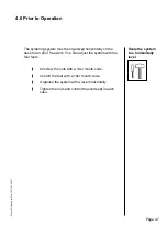
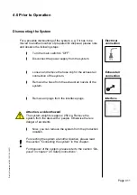
Dismounting the System
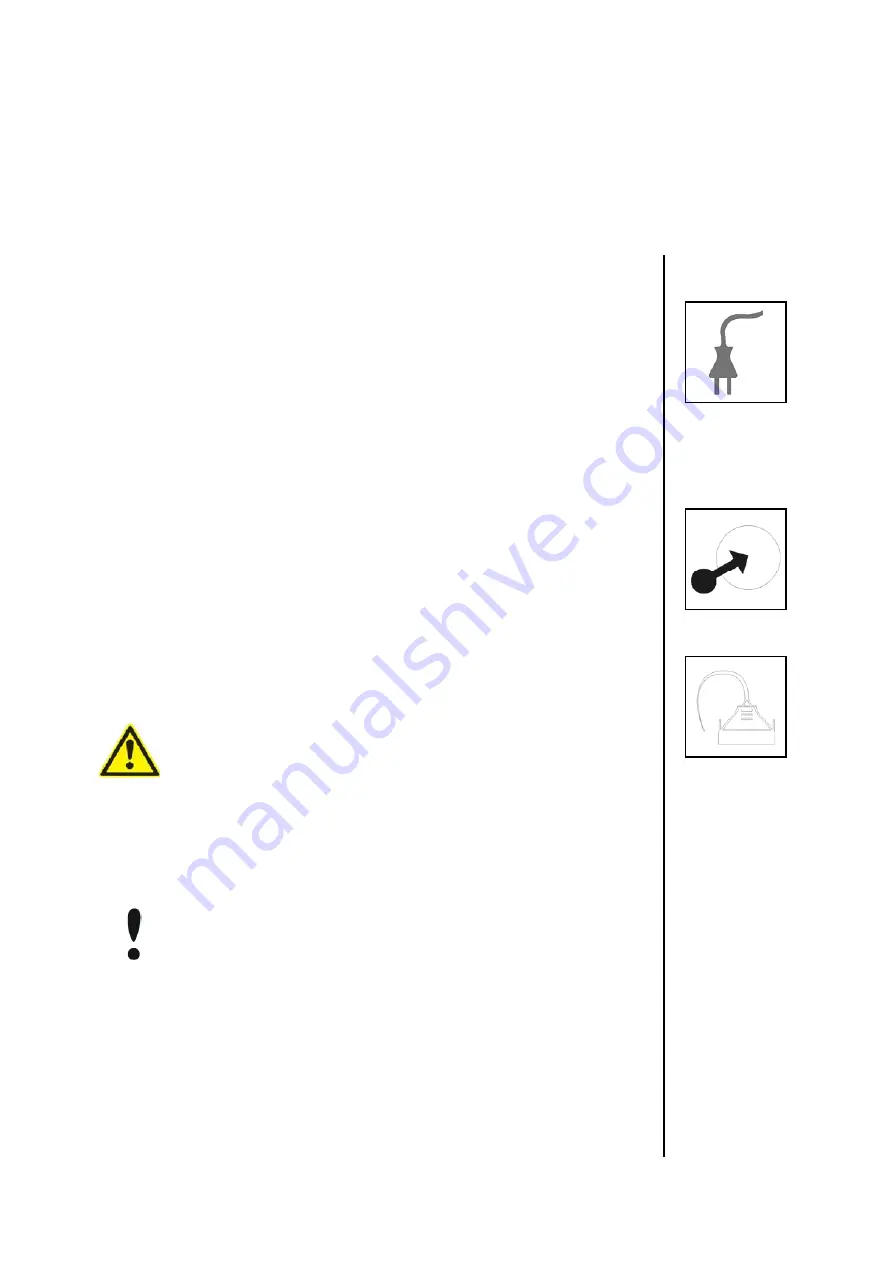
Electrical
connection
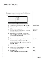
For a possible dismounting of the system, e.g. if it has to be
mo ved to another location or prepared for disposal, please note
and observe the following steps.
\
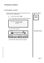
Turn the main switch to “OFF”.
\
Disconnect the power supply from the system.
\
Loosen and remove the hose clip for the exhaust air
connection of the system.
\
Remove the hose from the exhaust air nozzle of the
system.
\
Remove all plugs from the interface plugs.
Attention, accident hazard
The system weights is approx. 250 kg. Remove the
system from the desk with 2 people. Otherwise there is
dan ger of accidents.
\
Now, you can remove the system from the production
location.
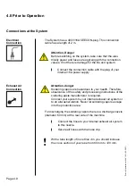
For erecting the system at another location, please read
the section “Connecting the system” in this chapter.
For disposal of the system ,please refer to the section “Dis-
posal” in chapter "2.0 Safety instructions”.
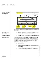
Exhaust air
connection
Interface
Summary of Contents for 548.10
Page 134: ...Page 12 1 12 0 Notes ...
Page 135: ...Page 12 5 12 0 Notes ...


