background image

11

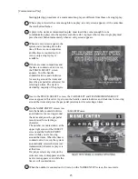
When carrying out the assembling and installation, follow the following 6-item sequence.

24mm

SECURING IN PLACE (ADJUSTER ADJUSTMENT)

POWER SUPPLY CONNECTION

TURNING POWER ON

ASSEMBLING CHECK

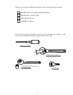
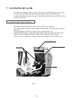
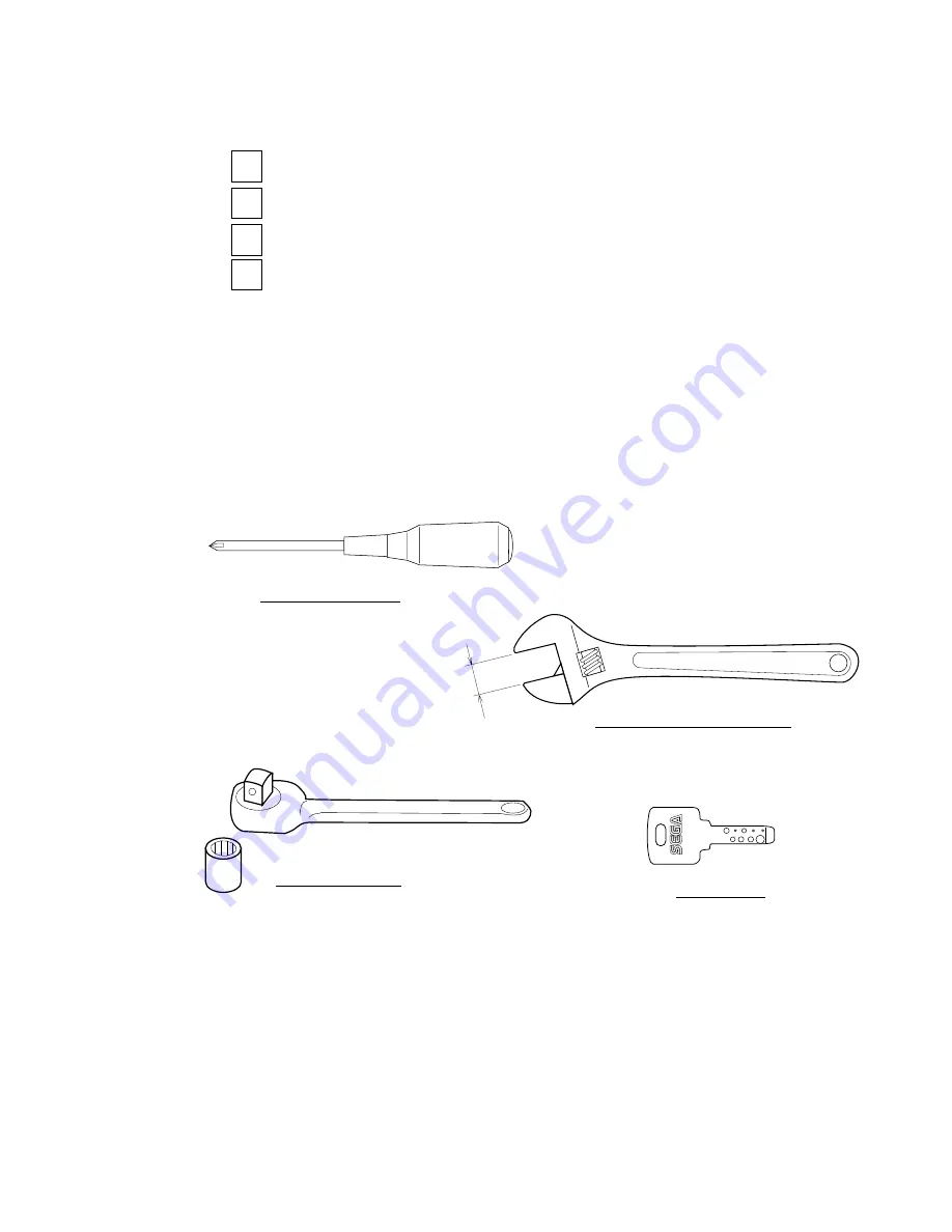
The master key (accessories) in addition to the tools such as a Phillips type screwdriver, wrench,
socket wrench and Ratchet Handle are required for the assembly work.

SOCKET WRENCH,(M8 hexagon bolt)
RATCHET HANDLE

WRENCH (for M16 hexagon bolt)

Phillips type screwdriver

KEY MASTER

1

2

3

4

Summary of Contents for 999-1108

Page 1: ...2ND PRINTING MARCH 01 MANUAL NO 999 1108 Owner s Manual Owner s Manual Owner s Manual Owner s Manual Owner s Manual SEGA ENTERPRISES INC USA Standard Version...

Page 2: ...vent a warranted part described above fails shall be at its option to replace or repair the defective part during the warranty period For Warranty claims contact your Sega Distributor Should the Selle...

Page 3: ...herein stated Instructions for work are explained by paying attention to the aspect of accident prevention Failing to perform work as per the instructions can cause accidents In the case where only th...

Page 4: ...should be performed only be those technical personnel who have knowledge of electricity and technical expertise Be sure to adjust the monitor projector properly Applies only to the product w monitor...

Page 5: ...FTER SHIFT LEVER 10 1 REMOVING THE 4 SPEED SHIFTER 10 2 REPLACING THE SWITCH 11 ACCELERATOR BRAKE 11 1 ADJUSTING AND REPLACING THE V R 11 2 GREASING 12 COIN SELECTOR 13 REPLACING THE FLOURESCENT LAMP...

Page 6: ...hased from SEGA ENTERPRISES INC U S A CUSTOMER SERVICE 45133 Industrial Drive Fremont California 94538 U S A Phone 415 701 6580 Fax 415 701 6594 Use of this product is unlikely to cause physical injur...

Page 7: ...so participate in the servicing and control of the equipment through such routine work as equipment assembly and installation servicing and inspections replacement of units and consumables etc within...

Page 8: ...ower cord If damaged the power cord can cause a fire or electric shock In case the power cord is damaged ask for replacement through where the product was purchased from or the office herein stated Us...

Page 9: ...nsure that this product is compatible with the location s power supply voltage and frequency requirements A plate describing Electrical Specifications is attached to the product Non compliance with th...

Page 10: ...prevent injury resulting from the falling down accident during game play be sure to secure the minimum area for operation Be sure to provide sufficient space so as to allow this product s ventilation...

Page 11: ...er to avoid accidents check the following before starting the operation To ensure maximum safety for the players and the customers ensure that where the product is operated has sufficient lighting to...

Page 12: ...se of an apparatus when walking Those who have high blood pressure or a heart problem Those who have experienced muscle convulsion or loss of consciousness when playing video game etc Those who have a...

Page 13: ...s on so as not to touch the operating unit while in play Failure to observe this may cause bodily contact with the player and trouble between the customers Caution the player so as not to hold a child...

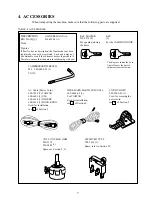
Page 14: ...s to purchase it Therefore ensure that the part is in safekeeping with you CORD CLAMP 280 5009 01 1 Used for securing the power cord see 4 of Section 5 AC Cable Power Cord 600 7228 1 TAIWAN 600 6695 1...

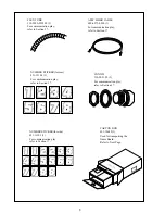
Page 15: ...fer to Section 17 CARTON BOX 601 10642 1 Used for transporting the Game Board Refer to Next Page CHECK SIDE CONN 22 310 5051 22 2 For communication play refer to Section 17 NUMBER STICKER for rear 421...

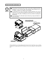
Page 16: ...in a Carton Box Otherwise the request is not acceptable Put the Shield Case in the Carton Box by paying attention to the correct direction as per the following instructions and as shown by the instru...

Page 17: ...and short circuit hazards This work should be performed by the Location s Maintenance Man or Serviceman Performing work by non technical personnel can cause a severe accident such as electric shock F...

Page 18: ...ER SUPPLY CONNECTION TURNING POWER ON ASSEMBLING CHECK The master key accessories in addition to the tools such as a Phillips type screwdriver wrench socket wrench and Ratchet Handle are required for...

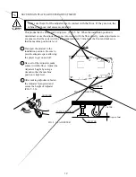
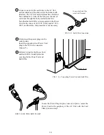
Page 19: ...height of Adjuster FIG 5 3 b FIG 5 3 a BOTTOM VIEW FIG 5 3 b ADJUSTER Make sure that all of the adjusters are in contact with the floor If they are not the cabinet can move and cause an accident This...

Page 20: ...with earth is used This product is equipped with the earth terminal Connect the earth terminal and the indoor earth terminal with the prepared cable If the grounding work is not performed appropriatel...

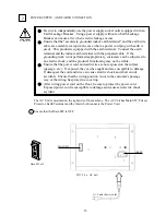
Page 21: ...procedure is not necessary Connect the Earth Wire to the Earth Terminal FIG 5 4 b Earth Wire Connection Firmly insert the power plug into the socket outlet Insert the opposite side of Power Cord plug...

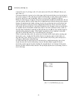
Page 22: ...n is completed that is the handle automatically stops at the center position Failure to observe this may affect the handle s operability and the handle s force feedback force feedback against crashing...

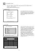
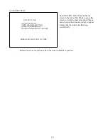
Page 23: ...G CHECK C R T TEST PAGE 1 0 31 RED GREEN BLUE WHITE PRESS SERVICE BUTTON TO ANOTHER PAGE PRESS TEST BUTTON TO EXIT 12345678901234567890123456789 12345678901234567890123456789 1234567890123456789012345...

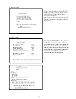
Page 24: ...ed Check if the sound is satisfactorily emitted from each speaker and the sound volume is appropriate SOUND TEST MAIN SPEAKER LEFT MAIN SPEAKER RIGHT OPTION SPEAKER LEFT OPTION SPEAKER RIGHT EXIT SELE...

Page 25: ...ch output unit such as lamps and wiring connections are tested to appear Ensure that the output unit functions satisfactorily Perform the above inspections also at the time of monthly inspection OUTPU...

Page 26: ...t before transporting Lifting up the product in an attempt to cross the step like differences in an as is assembled condition may damage the unit s joining portions and cause a personal injury resulti...

Page 27: ...he bass shaker do not output an advertise sound You can activate or deactivate an advertise sound output function on the test mode screen FIG 7 a 7 CONTENTS OF GAME The following explanations apply to...

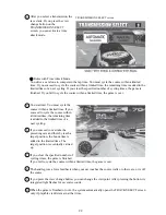
Page 28: ...you insert the coins enough for one play the credit number disappears and a SELECT screen appears TRACK SELECT CAR SELECT and TRANSMISSION SELECT screens appear in this order Turn the handle countercl...

Page 29: ...e If you succeed to cycle the course within a limited time the remaining time is added to the limited time of a next cycling If you succeed to overtake the preceding cars and thereby reach a target po...

Page 30: ...the gas pedal accelerator for selecting an item The track is decided by majority of the players Next to the TRACK SELECT screen the CAR SELECT and TRANSMISSION SELECT screens appear in this order Agai...

Page 31: ...op player can add the time remained after a cycling to the limited time of a next cycling When the top player clears the specified number of cycling times the game is finished If a player fails to cyc...

Page 32: ...h unit periodically perform the tests and data check When installing the machine initially or collecting cash or when the machine does not function correctly perform checking in accordance with the ex...

Page 33: ...n the IC Board Choose MEMORY TEST in the MENU mode to allow the MEMORY test to be performed In this test PROGRAM RAMs ROMs and ICs on the IC Board are checked Periodically perform the following 1 MEMO...

Page 34: ...lost BASE SHAKER Output Adjustment Volume FIG 8 1 a SWITCH UNIT 8 1 SWITCH UNIT AND COIN METER Adjust to the optimum sound volume by considering the environmental requirements of the installation loca...

Page 35: ...ND VOLUME Adjusts the sound volume of the left and right speakers on the control panel SOUND VOLUME Adjusts the sound volume of the left and right speakers on the seat backrest BASE SHAKER Output Adju...

Page 36: ...TO EXIT 8 2 SYSTEM TEST MODE A SYSTEM TEST MODE MENU Press TEST Button to enter the TEST MODE and the following Menu screen will be displayed Press SERVICE Button to move the arrow to the desired item...

Page 37: ...o the MENU screen JVS TEST DISPLAY CONFIG EXIT NODE 1 1 SWITCH SYSTEM ________ PLAYER1 _____________ PLAYER2 _____________ COIN SLOT1 0000 SLOT2 8000 ANALOG CH1 0000 CH2 0000 CH3 0000 CH4 0000 CH5 000...

Page 38: ...put from the front right speaker OPTION SPEAKER LEFT Output from the rear left speaker OPTION SPEAKER RIGHT Output from the rear right speaker Front speakers are located on the control panel Rear spea...

Page 39: ...901234567890123456789 12345678901234567890123456789 12345678901234567890123456789 12345678901234567890123456789 12345678901234567890123456789 12345678901234567890123456789 C R T TEST PAGE 2 PRESS SERV...

Page 40: ...st mode and eventually you cannot play the game CABINET TYPE 1PLAYER 8PLAYERS Always set to 1PLAYER ADVERTISE SOUND ON OFF Set to ON or OFF that enables to output or not an advertise sound from the sp...

Page 41: ...ts whether Coin Chute is used in common by all players or separately allocated to each player in case 2 or more Coin Chutes are incorporated COMMON This setting is for common use by plural players IND...

Page 42: ...many coins are needed for one credit 1 9 BONUS ADDER determines how many coins should be inserted to obtain one SERVICE COIN COIN CHUTE 1 MULTIPLIER COIN CHUTE 2 MULTIPLIER sets how many tokens one C...

Page 43: ...S 3 CREDITS SETTING 17 3 COINS 1 CREDIT 3 COINS 1 CREDIT SETTING 18 4 COINS 1 CREDIT 4 COINS 1 CREDIT SETTING 19 1 COIN 1 CREDIT 1 COIN 1 CREDIT 2 COINS 2 CREDITS 2 COINS 2 CREDITS 3 COINS 3 CREDITS 3...

Page 44: ...COINS 2 CREDITS 3 COINS 3 CREDITS 4 COINS 4 CREDITS 5 COINS 6 CREDITS SETTING 27 FREE PLAY Table 2 COIN CREDIT SETTING COIN CHUTE INDIVIDUAL TYPE COIN TO CREDIT 1 COIN 1 CREDIT 2 COINS 1 CREDIT 3 COIN...

Page 45: ...QUENCE5 CREDIT SEQUENCE6 CREDIT SEQUENCE7 CREDIT SEQUENCE8 CREDIT EXIT XXXXXXXXXXXXXXXXXXXXX SEGA ENTERPRISES LTD DESCRIPTION OF SEQUENCE SEQ1 CREDIT TO 1 PLAYER START SEQ2 NOT USED SEQ3 NOT USED SEQ4...

Page 46: ...ANOTHER PAGE PRESS TEST BUTTON TO EXIT H BOOKKEEPING This allows such data as operating time No of coins inserted No of credits to be checked etc This test consists of 2 screens Pressing SERVICE Butto...

Page 47: ...the SYSTEM MENU screen NOTE The same screen appears also in the GAME TEST MENU screen to clear the operating data BACKUP DATA CLEAR YES CLEAR NO CANCEL SELECT WITH SERVICE BUTTON AND PRESS TEST BUTTON...

Page 48: ...re correctly set the clock in the CLOCK SETING screen YEAR MONTH DAY HOUR and MINUTE are set for SEGA HIKARU BD Select the desired item with SERVICE Button and press TEST Button to increase the value...

Page 49: ...Press the service button to move the mark to any desired item and press the test button Then the selected item s screen appears In the screen use the service button and the test button similarly to i...

Page 50: ...s an analog value Make sure that the value can smoothly change as you operate the input device If not smoothly readjust the volume or replace it with a new one See Chapter 10 and 12 GEAR POSITION indi...

Page 51: ...integrated with the START and VIEW CHANGE buttons and base shaker by using the screen Item is automatically changed or selected in turn Make sure that the corresponding output device can normally ope...

Page 52: ...ESS TEST BUTTON FORCE Indicates the intensity of the force feedback The larger number the more intense force feedback FORCE TEST Tests the performance of the motor of the steering motor unit Intensity...

Page 53: ...IGNMENTS This screen enables to set the volume value of the steering wheel handle In other words this screen sets the volume value of the steering wheel s center position for a straight ahead directio...

Page 54: ...MIN 40 MAX 40 DEFAULT 0 GAS 0 0 MIN MAX UP DOWN EXIT SELECT WITH SERVICE BUTTON AND PRESS TEST BUTTON Ec BRAKE ASSIGNMENTS This screen enables to set the volume value of the brake pedal The MIN indic...

Page 55: ...he latter features moving from course to course in the race NORMAL This is a standard setting Selection of the extra course is explained only after you have totally played 1 000 times and at the end o...

Page 56: ...o DRIVER or REAR SPEED DISPLAY Sets the unit used to display the speed You can set it to KM H OR MPH SEAT NUMBER Sets the number of the cabinets interconnected for a communication play Arrange them an...

Page 57: ...GAMES 0 PLAY TIME 0D 0H 0M 0S AVERAGE PLAY TIME 0M 0S LONGEST PLAY TIME 0M 0S SHORTEST PLAY TIME 0M 0S PLAY TIME HISTOGRAM 0M 0S 1M59S 0 2M 0S 2M29S 0 2M30S 2M59S 0 3M 0S 3M29S 0 3M30S 3M59S 0 4M 0S 4...

Page 58: ...SSION SELECT Displays the number of selection times by transmission type BOOKKEEPING 2 2 DRIVER SELECT Steve Park 0 Rusty Wallace 0 Dale Earnhardt 0 Bobby Hamilton 0 Terry Labonte 0 Mark Martin 0 Mich...

Page 59: ...e mark to YES CLEAR item and press the test button When the system completes clearing a COMPLETED message appears on the screen Press the test button again to return to the GAME TEST MENU screen Press...

Page 60: ...use a serious injury such as a fracture When performing work such as parts replacement other than those specified in this manual be sure to contact where you purchased the product from and confirm the...

Page 61: ...l in the direction allowing the car to advance straight forward and ensuring the D CUT FACE of the Volume shaft is oriented as shown Tighten the 2 screws to secure the VR BASE Turn on power Set the Ce...

Page 62: ...SE from the HANDLE MECHA Take out 2 screws from the VR BASE reverse side to remove the Volume together with VR Bracket from the VR BASE Remove the Volume from VR Bracket and replace PHOTO 9 1 b VR BAS...

Page 63: ...ashers FIG 9 1 b Turn on power Set the Center Value of the Volume in the TEST mode In the TEST mode check to see if the Volume Value varies smoothly in accordance with the steering wheel operation Aft...

Page 64: ...ouch undesignated places Touching places not designated can cause electric shock or short circuit This work should be performed by the Location s Maintenance Man or Serviceman Performing work by non t...

Page 65: ...h other Disconnect the connectors from each other Uncouple the 4 speed shifter When replacing it to an original position be careful about the installation direction The side with the wires must face t...

Page 66: ...hes Be sure to check which Switch malfunctions prior to performing work Remove 4 speed Shifter as per procedure 10 1 Disconnect the wiring connected to the Microswitch Take out 2 screws to replace the...

Page 67: ...e parts to come into contact resulting in an electric shock a short circuit and a fire If Accel and Brake operation is not satisfactory adjustment of Volume installation position or Volume replacement...

Page 68: ...11 1 c Remove the Base and Gear to replace the Volume Adjust the Volume as per the previous page after replacing Once every 3 months apply greasing to the Spring and Gear mesh portion For spray greas...

Page 69: ...e every month when performing the Coin SW Test simultaneously check the following Does the Coin Meter count satisfactorily Does the coin drop into the Cashbox correctly Is the coin rejected when inser...

Page 70: ...91 1311 16 891 1312 16 891 1109 16 020X1877 005 890 1007 00 891 2216 16 890 1206 02 BASE PLATE ASSEMBLY KEP NUT SCREW FLAT HEAD M S MICROSWITCH ASSEMBLY NUTKEPS 8 32 X 5 16 HEX REJECT FLAP REJECT BEZE...

Page 71: ...64 Tom Happ Ph 847 593 6161 ext 107 tom happ happcontrols com Fx 847 956 2091 Happ Controls 106 Garlisch Drive Elk Grove IL 60007 Visit our website http www happcontrols com Guardian Hasp 30 2400 200...

Page 72: ...odified to accomodate a Mars 2000 series upstacker A 2000 series stacker can be added by simply remov ing the cut out plate This one entry door can be ordered through Happ Controls or one of Happ Cont...

Page 73: ...66 Coin door shown with optional dollar bill validator inserted...

Page 74: ...of the designated rating Using lamps of undesignated rating can cause a fire or malfunctioning To perform work safely and securely be sure to prepare a step which is in a secure and stable condition P...

Page 75: ...The lamp is inside the wiring connecting portion Push and then turn the Lamp counterclockwise to remove On the rear side of the switch plate there is a metallic projection on the foot of each button...

Page 76: ...he interior parts can be performed on a pay basis CLEANING THE CABINET SURFACES When the cabinet surfaces are badly soiled remove stains with a soft cloth dipped in water or diluted with water chemica...

Page 77: ...NOK KLUBER L60 or GREASE MATE SEGA PART No 090 0066 After greasing move the Seat a few times forward and backward so as to allow the grease to be applied all over uniformly Be sure to wipe grease whic...

Page 78: ...ect The Circuit Protector functioned due to the momentary overload Image adjustment is inappropriate Affected by peripheral machines or the building s steel frames Sound volume adjustment is not appro...

Page 79: ...entered Failure of the volume The Fluorescent tube is burnt out The lamp is burnt out Communication cables are disconnected Communication cables are wrongly connected Communication play is wrongly set...

Page 80: ...prevent electric shock and short circuit hazards be sure to turn power off before performing work Be careful so as not to damage wirings Damaged wiring can cause fire electric shock and short circuit...

Page 81: ...he main cabinet Disconnect the connectors of all the wires between the shield case s filter board on the ASSY MAIN BD STD and the main cabinet Remove the 2 wing bolts that fix the base a wooden plate...

Page 82: ...wed however only for the Sega s service engineer Remove the 4 screws that fix the shield case onto the base a wooden plate and detach the former from the latter Remove the 2 screws each and detach the...

Page 83: ...3821 01 SAMURAI EXTEND SOUND BOARD 837 13629 MAIN BD JUMPER SETTING JP4 1 2 JP5 1 2 JP6 1 2 JP7 1 2 JP8 2 3 JP9 2 3 JP10 1 2 JP11 2 3 FIG 16 2 ROM BD JUMPER SETTING JP3 2 3 JP4 2 3 JP5 2 3 JP6 2 3 SCR...

Page 84: ...Power SW is OFF Failure to observe this can cause electric shock or short circuit Use care so as not to damage wirings Damaged wiring can cause electric shock or short circuit Do not touch undesignate...

Page 85: ...nnectors Use them to wire the communication cables between one game machine to the next thereby you can interconnect all the game boards For this wiring prepare in advance some standard accessories fl...

Page 86: ...pending on the number and arrangement of the interconnected game machines you may remove either or both of the 2 hole lids Fig 17 2a CONNECTOR BOX TRUSS SCREW 4 black M4 X 16 HOLE LID SCREW 2 black M3...

Page 87: ...e plastic nut to the connector At this time pass the communication cable through the flex tube ahead of time so as to allow the following work to be performed easily Fig 17 2 d Install the flex tube i...

Page 88: ...depending on the number of the game machines to interconnect Wire exactly according to the illustration below For the number other than in the illustration always connect the TX of one game machine to...

Page 89: ...ssible Contact the adjusters of all the game machines to the floor Sec 5 3 Connect the power cords and the grounding cables Sec 5 4 Put the number stickers on the game machines Facing the PTV screens...

Page 90: ...erform the SEAT NUMBER setting in the GAME ASSIGNMENTS screen Set the machines sequentially to No 1 No 2 No 3 and so on as applicable starting from the extreme left facing the monitor s front side Set...

Page 91: ...machine New settings by the MASTER game machine become effective to all the interconnected game machines If any setting is inadequate or if the communication cables are improperly connected the system...

Page 92: ...SIDE 6 COL 4 999 1077 DECAL SEAT RIGHT SIDE NOT SHOWN 999 1076 DECAL SEAT LEFT SIDE 6 999 1063 DECAL CONTROL PANEL 7 999 1078 PLASTIC SEAT BACK STICKER 8 999 1071 DISPLAY MARQUEE 9 999 1079 PLATE BLA...

Page 93: ...061 PLATE TUBE UPPER YELLOW 3 999 1060 S A SIDE TUBE YELLOW 4 999 1055 PAD RL 5 999 1056 PAD RR 6 NCR0 2501 REAR TUBE ASSY 7 NCR0 2052 HOLDER PIPE YELLOW NOT SHOWN 999 0167 LEG LEVELER 1 2 13 X 3 NOT...

Page 94: ...87 2 AC UNIT ITEM NO PART NO DESCRIPTION 1 999 1043 AC BRKT NOT SHOWN DYN 0402 NOISE FILTER BASE NOT SHOWN 421 8202 STICKER EARTH MARK 101 999 1044 AC INLET PANEL TYPE 104 999 0676 SW ROCKER J8 V B...

Page 95: ...88 3 FAN UNIT STR 1070 ITEM NO PART NO DESCRIPTION 1 105 5340 01 FAN BRKT LONG 101 260 0011 02 AXIAL FLOW FAN AC100V 50 60HZ 102 601 8543 FAN GUARD 201 000 P00312 W M SCR PH W FS M3 X 12 CONNECTOR...

Page 96: ...89 4 ASSY CONNECTOR PLATE NCR 1080 ITEM NO PART NO DESCRIPTION 1 NCR 1081 CONNECTOR PLATE 2 421 7515 STICKER FIBER CABLE TX RX 101 211 5479 01 CONN OPT JOINT 201 000 P00312 W M SCR PH W FS M3 X 12...

Page 97: ...ON 1 999 1045 SW BRKT 2 421 11297 STICKER SW UNIT NCR 3 999 1046 VR COVER 4 999 1050 COIN METER 101 509 5028 SW PB 1M 102 220 5179 VOL CONT B 5K OHM 103 601 0042 KNOB 22 MM 104 601 0460 PLASTIC TIE BE...

Page 98: ...M NO PART NO DESCRIPTION 1 SPG 2001 STEERING WHEEL 2 SPG 2002 STEERING EMBLEM 3 999 1070 PUSH BUTTON RECT VLT 57 2000 62 4 999 1069 PUSH BUTTON SMALL RND 57 2000 35 NOT SHOWN DYN 1209X HANDLE COLLAR N...

Page 99: ...92 7 ASSY HANDLE MECHA NCR 2100 D 1 2...

Page 100: ...G 2507 VR BRKT 8 SPG 2108 STOPPER BOLT 9 SPG 2109 STOPPER RUBBER 10 SPG 2453 KEY 4 X 4 X 40 11 ASK 3502 MOTOR SPACER 12 ASK 3503 MOTOR COLLAR 13 DYN 1270 STOPPER KEY 14 SLC 1130 ADJUST RING 15 SPG 245...

Page 101: ...0 ASSY ACCEL BRAKE 2 FRI 2201 FOOT REST FRI 3 NCR 2201 PEDAL BASE 201 030 000825 SB HEX BLT W S BLK M8 X 25 202 060 F00800 0B FLT WSHR BLK M8 203 050 H00800 HEX NUT M8 204 060 S00800 SPR WSHR M8 205 0...

Page 102: ...95 9 ASSY ACCEL BRAKE SPG 2200 D 1 2...

Page 103: ...2217 VR COVER 19 SPG 2219 GEAR STAY 20 SPG 2220 WSHR 21 SPG 2221 NEUTRAL STOPPER D 101 100 5263 BEARING 12 102 220 5484 VOL CONT B 5K OHM 220 5373 VOL CONT B 5K 104 601 7944 GEAR 15 105 310 5029 F15 S...

Page 104: ...97 10 ASSY 4SPEED SHIFTER NCR 2150 D 1 2...

Page 105: ...5252 BEARING ROLLER 25 102 100 5193 GROMMET 11 103 100 5242 BEARING FAI 8 104 509 5636 SW MICRO TYPE SS 5GL2T 105 601 0460 PLASTIC TIE BELT 100 MM 106 280 5306 SPACER FAI 6 X 30 107 280 5307 SPACER FA...

Page 106: ...99 11 ASSY SEAT NCR 2400 D 1 2 SCREW FASTENING TORQUE TO BE M8 Bolt for fastening plastic 8 3N m M8 Others 19 9N m M4 Sonic Lock Portion 0 9N m...

Page 107: ...105 130 5172 BASS SHAKER 106 280 5009 01 CORD CLAMP 21 107 280 5275 SR10 CORD CLAMP SR10 108 601 6981 009 CABLE BEAR L 009 109 601 6563 225 BUSH 2 4T 201 030 000816 S HEX BLT W S M8 X 16 202 030 0008...

Page 108: ...101 12 ASSY MAIN BD STD D 1 2 NOTE MAKE SURE THAT THERE IS NO WIRING ETC IN THE SLASH MARK PORTIONS...

Page 109: ...E 2 NCR 4050 ASSY SHIELD CASE NCR 3 105 5382 SHIELD CASE BRKT 101 400 5397 01 SW REGU FOR JVS VA 104 601 0460 PLASTIC TIE BELT 100 MM 201 000 P00412 W M SCR PH W FS M4 X 12 202 000 P00408 W M SCR PH W...

Page 110: ...103 13 ASSY SHIELD CASE NCR NCR 4050 D 1 2...

Page 111: ...105 5381 FLT BD BRKT FOR SEGA HIKARU 6 421 9174 STICKER CAUTION ANTISTATIC 7 421 10023 AAB STICKER BD SERIAL NUMBER AAB 8 421 10023 BBR STICKER BD SERIAL NUMBER BBR 9 441 314033 STICKER 833 14033 10 6...

Page 112: ...105 14 ASSY AMP BD NCR 4100 D 1 2 NOTE 1 MAKE SURE THAT THERE IS NO WIRING ETC IN THE SLASH MARK PORTIONS 2 Set the 838 13578 B jumper as illustrated JUMPER SETTING...

Page 113: ...60HZ 105 211 5305 C JMPR SCKT 106 280 5275 SR10 CORD CLAMP SR10 107 280 5009 01 CORD CLAMP 21 108 280 0419 HARNESS LUG 109 601 0460 PLASTIC TIE BELT 100 MM 201 000 P00445 W M SCR PH W FS M4 X 45 202 0...

Page 114: ...107 15 ASSY ELEC NCR 4200 D 1 2 NOTE 1 MAKE SURE THAT THERE IS NO WIRING ETC IN THE SLASH MARK PORTIONS 2 Set all the DIP switches 837 13844 B and 838 13366 C to OFF 102...

Page 115: ...0135 POWER TRANSFORMER ER 501 103 117 5225 FUSES 1 6 25 A SLOW BLOW 2 3A SLOW BLOW 1 15A SLOW BLOW 104 512 5046 15000 C P 15000MA CE UL 105 310 5029 K20 SUMITUBE F K 20MM 106 280 5009 01 CORD CLAMP 2...

Page 116: ...If the right hand side numeral of the code is 0 then the wire will be of a single color shown by the left hand side numeral see the above Note 1 If the right hand side alphanumeric is not 0 that part...

Page 117: ...VISIT OUR WEBSITE...

Page 118: ......

Reviews: