background image

6

www.seuservice.com

INSTALLATION INSTRUCTIONS

1)  First.  Remove all access panels from the game.  Locate the original game Logic PCB’s & Power

Supply and remove from the Cabinet by first disconnecting all harnesses from the boards.  (You need
only to splice in the Main Power (110v AC) into the 3-Pin Connector (GRN/WHT/BLK).)

2)  Remove all existing game harnesses (we suggest using New Jamma Harnesses (

NOT contained in the

kit

) to ensure reliability).

3)   Locate the most convenient and open area of the cabinet to mount the 

Capcom vs. SNK2 

  Naomi

System Assembly.  Make sure this area is free and clear of all cable harnesses and grounds, cable
clamps, etc.

Vacuum out or clean bottom of cabinet of dirt & miscellaneous parts (e.g.
screws, loose coins / tokens, etc.).

Remove all exterior decals and repair any cabinet damage.  Repaint
cabinet if necessary.  Remove the Monitor Plexi or if your game plexi has
Silk-screened artwork, you will need to strip it off.

4)   Connect the JAMMA Harnesses to the JVS-JAMMA Interface Boards.  Separate the wires from each

other (i.e. Control Panel, Video, Speaker, Power Supply).  Run the various harnesses to the part of the
cabinet they go to ensuring they are dressed properly & secured to the cabinet.  Locate the Volume/
Speaker/Coin Meter Cable and connect to your existing

 Switch Bracket

 or use the new one included

with the kit.  

Note:


If you are using a VGA Compatible Monitor you can run your VGA Cable directly

to the monitor or connect it to your JVS JAMMA Interface for RGB Conversion to your JAMMA
Cables.

5)   Remove  Marquee from cabinet and cut to fit the new

 Capcom vs. SNK 2 

 Marquee in place.


REPLACE

 old Joysticks & Buttons with the 

NEW

 ones supplied in Kit.

6)   First remove all Joystick and Button assemblies from the Control Panel.  Remove Lexan and Control

Panel Overlay.  Proceed to clean surface of the Control Panel by removing all adhesive and dirt.  Fill
in or plug up existing button holes to set up a blank work area for your new controls.

7)   Install the new Control Panel Overlay by carefully peeling off the paper backing and laying down on

the panel.  Smooth it out, starting in the center and working your way to the edges (removing all of
the trapped air pockets).  If necessary, cut the edges of the overlay excess and fold under panel.

8)   Cut out the button and Joystick Holes.  Install Joystick and buttons from kit into the Control Panel

and tighten down.  Connect all game harness wires to switches and buttons.

Summary of Contents for Capcom vs SNK 2

Page 1: ...EPT 01 MANUAL NO 999 1318 SEGA ENTERPRISES INC USA Universal Kit Kit Installation Instructions Service Manual Switchable FROM High Resolution 31K TO Standard Low Resolution 15 75K 1 2 PLAYER GAME www...

Page 2: ...VISIT OUR WEBSITE...

Page 3: ...CHASE XKT 0833 999 1326 999 1327 999 1328 999 1325 999 1329 Desc NAOMI POWER SUPPLY AUDIO POWER AMP 2 CH AUDIO XFORMER 120V JAMMA I O BD NAOMI USB CABLE VGA VIDEO CABLE ASSY CASE PC1 DIMM BD CABLE SCS...

Page 4: ...34 999 1335 999 1336 999 1337 999 1338 999 1339 999 1340 Desc MARQUEE ART INSTR SHEET PLAYER INSTR SHEET 2 CNTRL SIDE ART CTRL PNL OVERLAY DECAL BTTN LIGHT PNCH RED DECAL BTTN MIDDLE PNCH GRN DECAL BT...

Page 5: ...3 www seuservice com DESIGNED RELATED PARTS MARQUEE ART 999 1330 CTRL PNL OVERLAY 999 1334 INSTR SHEET 2 CNTRL 999 1332...

Page 6: ...R SHEET PLAYER 999 1331 DECAL BTTN LIGHT PNCH RED 999 1335 DECAL BTTN MIDDLE PNCH GRN 999 1336 DECAL BTTN HEAVY PNCH BL 999 1337 DECAL BTTN LIGHT KICK RED 999 1338 DECAL BTTN MIDDLE KICK GRN 999 1339...

Page 7: ...Square Connector at Game BD Yellow 5vdc Brown 3 3vdc White Gnd Step 2 You MUST USE THE COIN METER SUPPLIED WITH YOUR KIT to assure proper Coin acceptance A minimum 18 Gauge wire should be used from th...

Page 8: ...part of the cabinet they go to ensuring they are dressed properly secured to the cabinet Locate the Volume Speaker Coin Meter Cable and connect to your existing Switch Bracket or use the new one incl...

Page 9: ...just if necessary to 5 15v DCand 3 3vDC Measure the 12 to ensure the wires and voltages are in the correct position Turn power off Plug in the JAMMA Harness once again to the I O Boards The Attract Mo...

Page 10: ...in Meter Test Service Volume JAMMA Pin R JAMMA Pin 15 JAMMA Pin 1 Yellow Wire from Extra Harness 5v JAMMA Pin 8 _ Pin 1 Pin 5 Pin 4 To CN1 of Amplifier Board YEL RED WHT RED GRN RED From CN2 of Amplif...

Page 11: ...ot Used Not Used Not Used 12v Not Used 12v Not Used Key Key Coin Meter 1 Coin Meter 2 Not Used Not Used Not Used Not Used Not Used Not Used Video Red Video Blue Video Ground Video Green Video Sync Ser...

Page 12: ...formation Connector Description etc PSW2 PSW1 CN3 CN2 CN1 DIPSW1 Power Connectors VGA Level Video Out Preamp Level Audio Out Test Switch Service Switch 1 1 2 2 3 3 4 Setting for High Resolution 31KHZ...

Page 13: ...rt such a non usable disk into the GD ROM drive Otherwise the N inserted disk can not be ejected When cleaning a heavily contaminated disk use clean cloth that has been soaked in water and squeezed Th...

Page 14: ...of this game is for the North American countries only Europe version of this game is for the European countries only Sales export or operation outside these countries may b construed as copyright and...

Page 15: ...pill any liquids on the case Do not disassemble the case Always keep the connectors clean Do not disconnect the connectors cables or the harness while the NN N power is on Disassembling the case or re...

Page 16: ...N C COIN LOCK OUT 2 SP N C VIDEO GREEN VIDEO SYNC SERVICE SW N C COIN SW 2 START SW 2 2P UP 2P DOWN 2P LEFT 2P RIGHT 2P SHOT 1 2P SHOT 2 2P SHOT 3 2P SHOT 4 2P SHOT 5 GND GND A B C D E F H J K L M N...

Page 17: ...llowing is the default settings of COIN ASSIGNMENTS COIN CHUTE TYPEN COMMON COIN CREDIT SETTINGN 1 COIN CHUTE 1N 1 COIN 1 CREDIT COIN CHUTE 2N 1 COIN 1 CREDIT 3 Please refer to the following for the S...

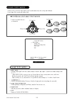
Page 18: ...the number changes from 0 to 1 Inside INPUT TEST you can test up to two Service Buttons In case your cabinet has only one Service Button please make sure if the 1P Service Button functions properly P...

Page 19: ...timer speed There are 4 levels in total As the number increases the time elapses quicker GAME SPEED Sets the game speed 5 levels are available As the number gets higher the game speed increases EVENT...

Page 20: ...al even to the people who had never played video games before For this universal appeal of the game we strongly recommend you to install this game in a large cabinet and place it at the front of your...

Page 21: ...Attached place 1 2 PART NO DESCRIPTION 1 840 0001F ASSY CASE NAO DIMM BD COM 2 KEY CHIP 1 2 840 0084B 01 DIMM BD NAO CPvsSNK2 PART NO DESCRIPTION 1 840 0004F ASSY CASE NAO DIMM BD COM RTOS 2 KEY CHIP...

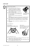
Page 22: ...avily contaminated disc use clean cloth that has been soaked in water and squeezed Then remove moisture with dry cloth When holding a disc be careful not to contaminate it with your fingerprints How t...

Page 23: ...please mention the Part No 610 0625 PART NO DESCRIPTION 1 2 3 4 610 0630 0008 GD SOFT KIT CPvsSNK2 ENG 1 NAOMI GDROM CPvsSNK2 2 KEY CHIP 3 420 6620 01 SERVICE MANUAL CPvsSNK2 ENG 4 253 5507 DISC CASE...

Page 24: ...g the Game Board refer to the CVT Manual and Instruction Manual PART NO DESCRIPTION ASSY CASE 1 2 840 0084D 01 ASSY CASE NAO CPvsSNK2 USA USA 840 0084D 02 ASSY CASE NAO CPvsSNK2 EXP OTHERS 840 0084D 0...

Page 25: ...N 8 of Jamma To Extra Yellow Wire COIN COUNTER JAMMA CONNECTIONS USED ARE VIDEO OUT SWITCH INPUTS SWITCH GROUND RETURNS COIN COUNTER OUTPUT NOTE THERE ARE TO BE NO CONNECTIONS MADE TO THE JAMMA INTERF...

Page 26: ...vent a warranted part described above fails shall be at its option to replace or repair the defective part during the warranty period For Warranty claims contact your Sega Distributor Should the Selle...

Page 27: ......

Reviews: