37
CONTROL PANEL
9
2
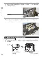
Center the steering wheel, and engage the gear while making sure that the D-cut fl at edge of the volume axis is
aligned in the direction indicated (see 9-2 FIG. 01).
3
Tighten the two screws and secure the VR base. Turn the steering wheel and check that the gears move smooth-
ly. Close and secure the control panel.
4
Switch on the unit. Be careful not to touch the steering wheel when doing so. After the unit is switched on, the
steering wheel undergoes automatic initialization.
5
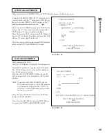
Confi gure the volume values on the INPUT ASSIGNMENTS screen in Game Test Mode.
It is recommended that the steering wheel volume be set to 80H±8H when the steering wheel is centered. Con-
fi rm that when the steering wheel is turned to the left the numbers decrease, and when it is turned to the right the
numbers increase.
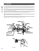
Replacement Procedure
When replacing the volume, you will also need to prepare three lengths of heat-shrinkable tubing (Part No.: 310-5029-F20), as well as use the wires
that are already soldered onto the volume. For this task, you will need a Phillips-head screwdriver (for M4 screws), a 2 mm hexagon wrench, an 11 to
12 mm adjustable wrench, wire cutter, knife, wire stripper, soldering iron, and work dryer.
1
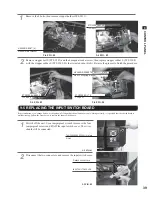
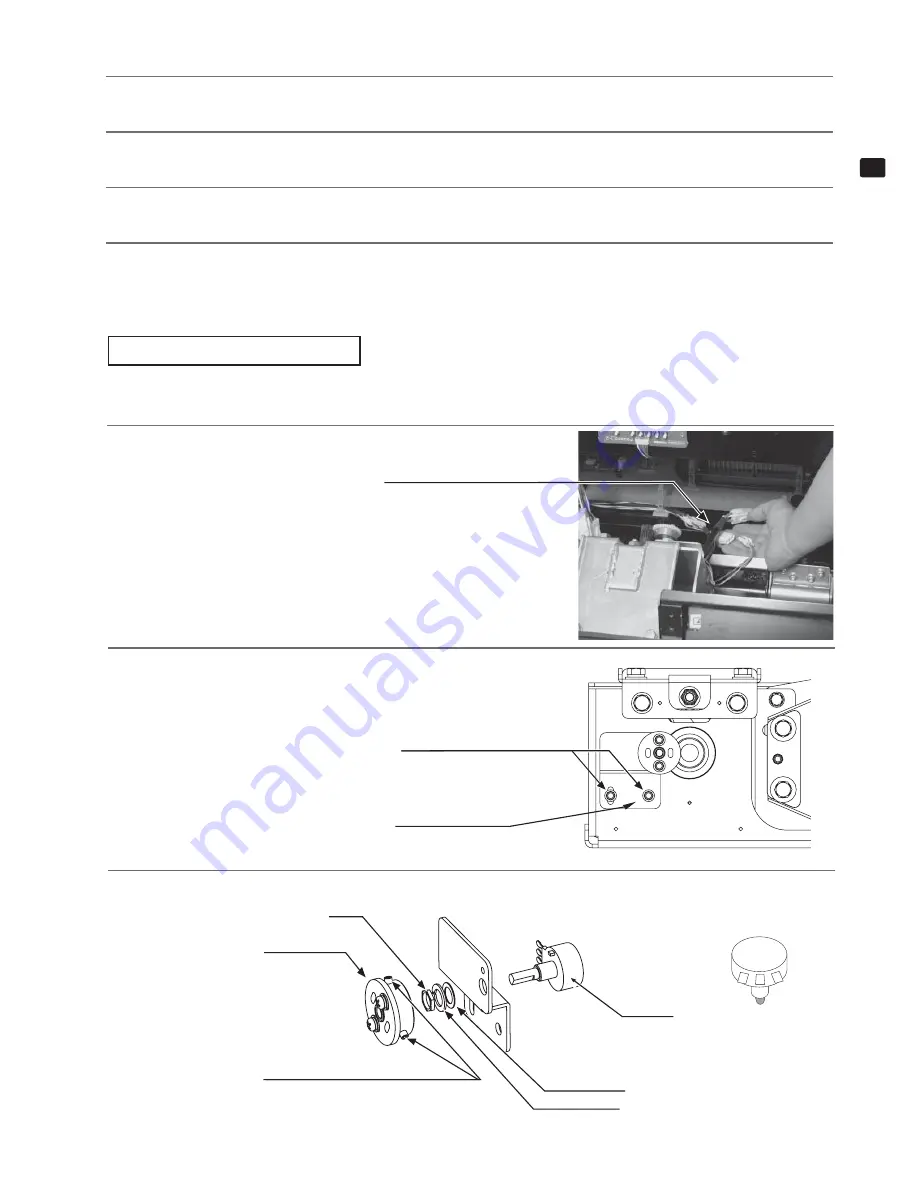
Detach the connector.
9-2 FIG. 02
Detach the connector.
WHITE 3P
2
Remove the two screws that secure the VR bracket and lift out the
volume with the bracket.
3
Loosen the screws on the gear holder, and detach the gear holder.
9-2 FIG. 04
SCREW (2)
M4x10, w/fl at & spring washers
VR BRACKET
220-5484
(Same as
220-5753)
FLAT WASHER
SPRING WASHER
GEAR HOLDER
NUT
HEXAGON SOCKET SCREW (2)
M4x8
9-2 FIG. 03
3 2 1
WIRE COLOR
OF POT.
3 = PINK
2 = GREEN
1 = BROWN
Summary of Contents for Initial D4
Page 1: ......


