39
CONTROL PANEL
9
9-4 FIG. 03
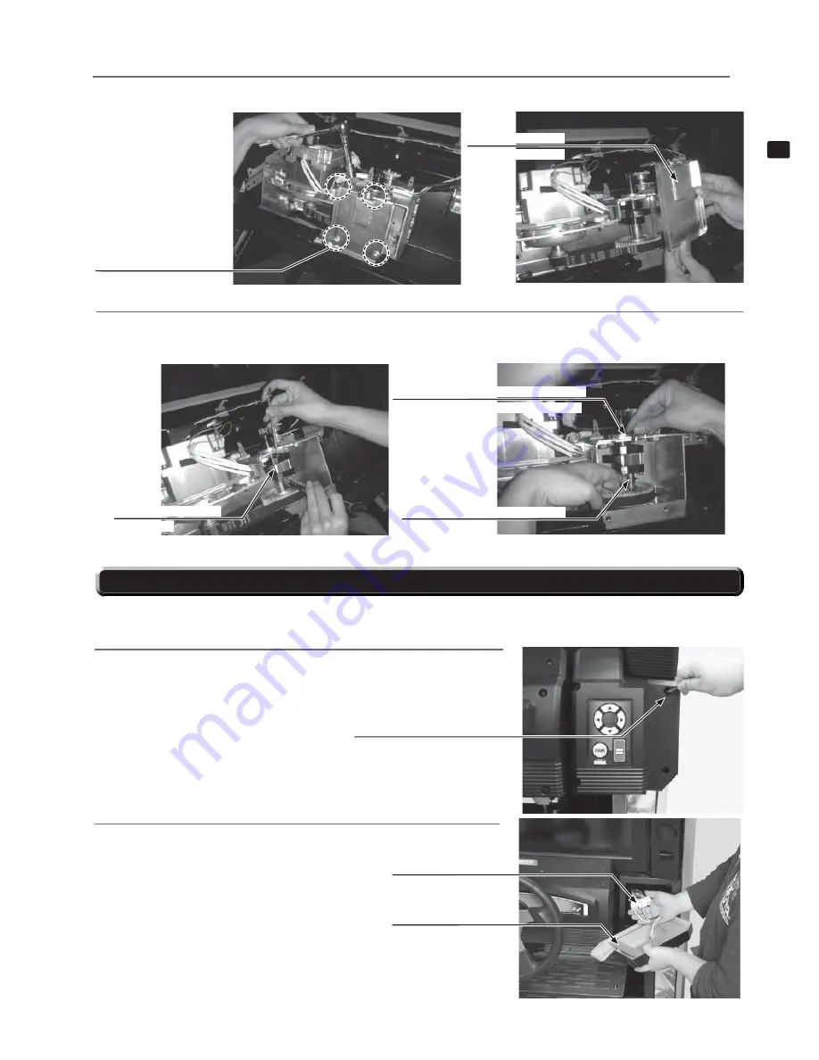
STOPPER RUBBER S
TFF-2508
1
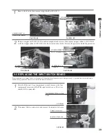
Remove the 4 bolts, then remove stopper holder (TFF-2511).
9-4 FIG. 01
HEXAGON BOLT (4)
M8x40, w/fl at washer
2
Remove stopper bolt S (TFF-2507) and the hexagonal socket screw, then replace stopper rubber S (TFF-2508)
with the stopper rubber S (TFF-2508-01) that is included in this kit. Reverse the process to fi nish the procedure.
9-4 FIG. 04
STOPPER BOLT S
TFF-2507
HEXAGON SOCKET SCREW (1), black
M6x12, w/spring washer
9-4 FIG. 02
STOPPER HOLDER
TFF-2511
If the start button, view change button, or the up/down/left/right directional buttons are not working correctly, it is possible that the switch board is
malfunctioning. Follow the steps below to replace the input switch board.
1
Switch off the unit. Use a tamperproof wrench to remove the four
tamperproof screws and lift off the input switch cover. The wires
should still be connected.
9-5 FIG. 01
9-5 FIG. 02
9-5 REPLACING THE INPUT SWITCH BOARD
2
Disconnect the two connectors, and remove the input switch cover.
Detach connectors.
INPUT SWITCH COVER
TAMPERPROOF SCREW (4), black
M4x10
Summary of Contents for Initial D4
Page 1: ......


