Installation and assembly instructions
6
2
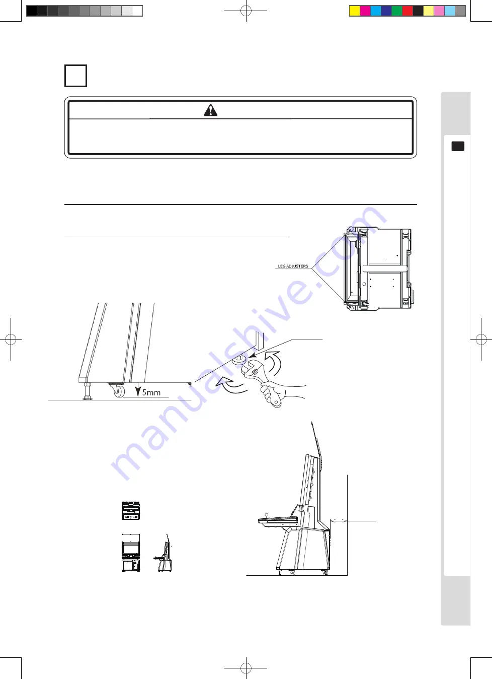
Fastening in the installation location (adjustment of the adjusters)
Make sure all adjusters touch the floor. If they do not, the cabinet could move and
cause an accident.
There are four casters and four adjusters on the bottom of the cabinet. Once the installation position is determined,
move the adjusters down to the ground and adjust them so that this product is level.
1
Move the machine to the installation position.
Figure6.1c Underside plan
150mm
Figure 6.1e
1/100 scale.
Refer to the layout leading to
the installation position.
Figure 6.1f
Allow space for air movement on
the side with ventilation openings.
2
Bring the adjusters into contact with the ground. Use a spanner to
adjust the four adjusters so that the product is held level.
Figure6.1c Underside plan
Adjuster
WARNING
Lindburg.indb 13
2/16/2007 19:12:07
Summary of Contents for Lindbergh Universal
Page 37: ...The monitor LCD display 31 11 List of setting items Lindburg indb 31 2 16 2007 19 12 24...
Page 60: ...54 Parts list 15 2 ASSY CABINET UR LCB 1000UK D 1 3 Lindburg indb 54 2 16 2007 19 12 43...
Page 61: ...Parts list 55 15 2 ASSY CABINET UR LCB 1000UK D 2 3 Lindburg indb 55 2 16 2007 19 12 43...
Page 63: ...Parts list 57 15 3 ASSY BASE CABINET LCA 1100UK D 1 2 Lindburg indb 57 2 16 2007 19 12 44...
Page 69: ...Parts list 63 15 8 ASSY MONITOR 32 LCA 1600UK D 1 2 Lindburg indb 63 2 16 2007 19 12 48...
Page 88: ...82 Overall wiring diagrams 18 D 2 2 Lindburg indb 82 2 16 2007 19 13 13...


