GAME BOARD
99
16
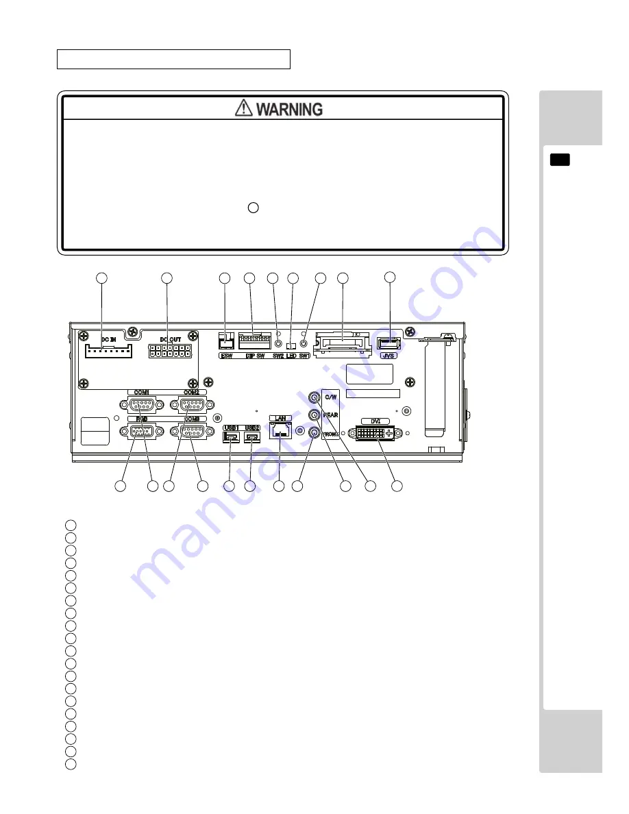
CONNECTORS, SWITCHES AND LED
● When connecting the connector, check the orientation and type carefully and
connect securely. The connector must be connected in the proper direction
and type. If it is connected in the wrong direction or indiscriminately at an
incline or connected erroneously (so that a load is applied), the
connector or its terminal pins could break, causing a short circuit or fire.
● Do not connect components to
9
JVS I/O that are not designated by SEGA.
Connecting unspecified components could cause an accident such as an
electric shock or fire.
1
2
3
2
20
2
19
2
18
2
17
2
16
2
15
5
6
4
11
9
2
12
2
13
2
14
7
8
10
Power input port
External power supply port
Test/Service button external input port
DIP SW (Dip switches)
Service button (SW2)
LED1, LED2 (From right to left: 1, 2)
Test button (SW1)
Key chip socket
JVS I/O port
DVI output
Center/Woofer lineout
Rear lineout
Front lineout
LAN port
USB port 2
USB port 1
Serial communication port 3
Serial communication port 2
Serial communication port 1
RGB output
1
2
3
4
5
6
7
8
9
10
12
13
14
15
16
17
18
19
20
11


