background image

 63

5.2.9.7.LANGUAGE  (For overseas version other than US, 

Australia, and Korea) 

 
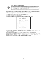
Select LANGUAGE to display the following screen and choose the language displayed on the screen 
message. Five languages (English/French/German/Italian/Spanish) are selectable. (Default setting: English) 
 

LANGUAGE Screen 


Use the SERVICE Button to move the cursor to LANGUAGE and press the TEST Button to choose your 
favourite language. 
 
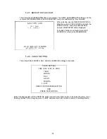
Move the cursor to EXIT and press the TEST Button to return to the Game Test Menu screen. 
 

Summary of Contents for The Maze of the Kings

Page 1: ...s product read this SERVICE MANUAL carefully to understand the contents stated herein After reading this manual be sure to keep it available nearby the product or somewhere convenient in order to be a...

Page 2: ...3 10 REPLACEMENT OF FLUORESCENT LAMP AND OTHER LAMPS 23 3 10 1 FLUORESCENT LAMP REPLACEMENT 23 3 10 2 LAMP REPLACEMENT 24 3 11 TROUBLESHOOTING 25 3 12 CONTROLLER 26 3 12 1 REPLACING THE MICRO SWITCH 2...

Page 3: ...1 3 PRICE OF PLAY SETTINGS Austria Czech Denmark Norway Israel France2 68 7 DESIGN RELATED PARTS 69 8 PARTS LIST 70 8 1 SPX 0000UK TOP ASSY SPHINX DX 70 8 2 SPX 0500UK ASSY PTV 71 8 3 SPX 0520UK ASSY...

Page 4: ...hazard will be created if the machine is operated while any parts have been removed Do not operate the product if any doors lids or protective covers become damaged or lost SEGA is not liable in any w...

Page 5: ...cuts etc on the external surfaces of the product Are castors and leg adjusters present and undamaged Do the power supply voltage and frequency requirements meet with the local supply Are all wiring c...

Page 6: ...ied SEGA product has warning displays on stickers labels or printed instructions adhered attached to or incorporated in the places where hazardous situations can arise The warning displays are intende...

Page 7: ...ic assemblies electro mechanicals servicing controls spare parts etc as regards Maze Of The Kings a new SEGA product This manual is intended for those who have knowledge of electricity and technical e...

Page 8: ...the warranty The PCB s contain static sensitive devices that could be damaged Always return a faulty part to your distributor with adequate packaging and protection When removing the plug from the mai...

Page 9: ...PARTS Width cm Length cm Height cm Weight kg PTV 114 53 158 91 BILLBOARD 114 40 40 19 With POP Panel 134 5 74 MAIN CABI DX 114 96 8 93 9 87 GUN CABI 54 8 101 98 7 40 When Assembled 114 134 5 164 6 22...

Page 10: ...INST PLATE MAZ DX MULTI 101 290094 0 8 WRAP BUBBLE SM 201 030 000850 SB 4 M8X50 BLT W S BLK FENCE L R 2EA 202 030 000830 SB 8 M8X30 BLT W S BLK FENCE L R 4EA 203 029 F00625 0B 4 M6X25 SKT CSK BLK 205...

Page 11: ...original card transit box THERE ARE NO USER SERVICEABLE PARTS INSIDE Failure to return the GAME BOARD in this manner may invalidate the warranty Pack the ASSY SHIELD CASE ALONG WITH DIMM BOARD in the...

Page 12: ...d transit box THERE ARE NO USER SERVICEABLE PARTS INSIDE Ensure the GD ROM Disk is removed and the GD ROM Drive Lid is replaced on the unit with fixing screw before packaging Also remove the GD ROM Dr...

Page 13: ...occur Do not attempt to complete this work alone a minimum of 2 people are required Only QUALIFIED SERVICE PERSONNEL should carry out assembly When carrying out the assembly work follow the procedure...

Page 14: ...ions shown It is imperative that the earth eyes are connected to the plate at the bottom of the PTV 2 Lift the PTV forwards onto the PTV Cabinet using a minimum of four workers to lift the PTV plus a...

Page 15: ...GUN CABINET 1 Secure Gun Panels to Bracket using 4 M6 x 25 Socket Head Countersink Black Bolts Pt No 029 F00625 0B 2 per Panel 3 7 1 4 ATTACH THE GUN CABINET 1 After fitting the guard rails to the gu...

Page 16: ...ng the M4x30 screws provided 3 7 1 5 FIT POP PANEL TO BILLBOARD 1 Attach the Pop Panel Bracket SPX 0526UK to the top of the Billboard using the 3 Black M4x16 Truss Screws and Washers supplied at locat...

Page 17: ...m the billboard to the PTV It is imperative that the earth eye is connected to the top plate of the PTV 3 Place the billboard onto the PTV and slide it forward under the catches 4 Fix the billboard in...

Page 18: ...ration This machine has 4 castors and 8 leg adjusters When the installation position is decided unscrew the leg adjusters so that they raise each castor a minimum of 5mm from the floor Make sure the m...

Page 19: ...ecific manufacturers installation instructions for that coin mechanism To fit the door to the machine follow the procedure below Loosen all of the bolts on the frame that secure the clips Turn all cli...

Page 20: ...er mech s micro switch Attach the 2 way mate and lok plug to the 2 way mate and lok cap provided Attach one 15 way connector to Validator A and the other to Validator B on the credit board MARS MS111B...

Page 21: ...he machine has been fully assembled and fixed in position it is ready to be connected to the power supply 1 The socket outlet shall be installed near the equipment and shall be easily accessible 2 Ins...

Page 22: ...there are no faults Selecting the MEMORY TEST on the test mode screen causes the on board memory to be tested automatically The game board is satisfactory if the display beside each IC No shows GOOD T...

Page 23: ...is displayed to indicate satisfactory operation Selecting PLAYER 1 or 2 should cause the relevant lamp to light if connections etc are satisfactory The GUN ADJUSTMENT parameters should now be set Refe...

Page 24: ...ng the machine retract the leg adjusters fully and ensure the casters make contact with the floor During movement pay careful attention so that the casters or leg adjusters do not damage any other cab...

Page 25: ...chine to protect the user and the machine from damage Only replace the fuse once you have removed the cause of its failure Detailed below is a list of the fuses used their location and if relevant PCB...

Page 26: ...id injury The Fluorescent Lamp can get hot and cause burns Allow the Lamp to cool before touching it Only QUALIFIED SERVICE PERSONNEL should replace lamps 3 10 1 FLUORESCENT LAMP REPLACEMENT 1 Remove...

Page 27: ...lift the control panel cover up until it is possible to disconnect the wire harness plugs attaching the start switches to the cabinet 3 Turn the control panel cover over and remove the micro switch f...

Page 28: ...stments SEE SECTION 3 7 5 The on screen image of the monitor sways and or shrinks The power source and voltage are not correct Make sure that the power supply and voltage are correct Sound is not emit...

Page 29: ...controller parts are replaced Refer to the diagram on the following page when working on the controllers 3 12 1 REPLACING THE MICRO SWITCH 1 Disassemble the controller 2 Pullout the micro switch from...

Page 30: ...27...

Page 31: ...SERVICE PERSONNEL The GD ROM Service Manual supplied with this product instructs you to remove the Key Chip when shipping the NAOMI Board However this product employs a dedicated NAOMI Board therefore...

Page 32: ...29 6 Remove all connectors from the filter board of the NAOMI Board Also remove the GD cable connector from the DIMM Board 7 Remove four screws securing the NAOMI Board to the base...

Page 33: ...binet and remove the GD ROM Drive from the ASSY MAIN BD as follows i Following the above procedure steps 1 to 5 take out the ASSY MAIN BD 2 Remove the GD cable connector and the power cord connector f...

Page 34: ...31 3 14 COMPOSITION OF THE GAME BOARD...

Page 35: ...tion may cause a fire or electric shock Only QUALIFIED SERVICE PERSONNEL should carry out periodic checks DESCRIPTION WHAT TO CHECK INTERVAL MONITOR PROJECTOR Clean screen Check adjustment Weekly Mont...

Page 36: ...be a fault While power is connected the billboard is continuously lit and demonstration footage and ranking data are displayed on the screen This advertise mode will be accompanied by sound from both...

Page 37: ...t lies hidden the route to the treasure changes Two treasure hunters with magic rods in hand Can they miraculously defeat the guardians and avoid countless traps to retrieve the hidden treasure 4 1 3...

Page 38: ...have been inserted for a single player game the INSERT COIN S message at the bottom of the screen will change to PRESS START BUTTON and both Start buttons will flash NB Up to nine credits can be coun...

Page 39: ...ly less powerful SPARK This effect provides a balance between shot strength and frequency FIRE This effect is the most powerful but allows the least number of shots 2 Equipment Selection Select equipm...

Page 40: ...Number of Rod Effects 5 Player One Number of Stones 6 Player One Number of Lives Remaining 7 Player Two Score 8 Player Two Equipment Selected 9 Player Two Number of Rod Effects 10 Player Two Number o...

Page 41: ...ses a certain number of lives The player loses a life each time they suffer an enemy attack biting clawing slashing or hitting A sight appears each time players battle a boss character Players lose on...

Page 42: ...fe to increase the number of lives by one Stones Collect three Stones to increase the number of lives by one Treasure Item This is enemy treasure Reveal the Treasure by defeating the enemy for bonus p...

Page 43: ...uire the Boss s treasure During a minigame follow the instructions that appear on the screen Players can increase their scores by completing the minigame and acquiring the treasure Rankings The Stage...

Page 44: ...and lives 4 1 5 6 Game Over The following conditions result in GAME OVER ii Reduction of players lives to zero iii Clearing of Stage Three 4 1 5 7 Continue To continue when a player s lives are reduce...

Page 45: ...Stop Multiple Enemies in their Tracks Simultaneous attacks by multiple enemies are extremely dangerous Be sure to create situations where they can be dealt with one on one Aim at the Shoulders and Leg...

Page 46: ...amps 5 2 9 2 In the MEMORY TEST mode check all of the IC s on the IC BD 5 2 1 Monthly MEMORY On the TEST MENU screen choosing the MEMORY TEST allows self test to be performed In this test RAM ROM are...

Page 47: ...as function during TEST mode Refer to the later section detailing TEST mode SERVICE BUTTON SERVICE SW Gives credits without registering on the coin counter Also used during TEST mode DEMAG Eliminates...

Page 48: ...s for IC Board function checks monitor adjustment coin assignments etc Please also refer to the Monitor Service Manual supplied with this product The following assignments however should be designated...

Page 49: ...the RAM functions to be checked on the Naomi Main Board GOOD is displayed for satisfactory RAMs BAD is displayed if any irregularities are found During test TESTING NOW is displayed Press the TEST but...

Page 50: ...47 5 2 2 JVS TEST...

Page 51: ...re darkest at the leftmost end becoming brighter towards the right in 31 graduations Monitor brightness is satisfactory if the white colour bar is black at the leftmost end and white at the rightmost...

Page 52: ...ICE button to move the cursor to the desired item 2 Press the TEST button to change the setting 3 Upon finishing the settings move the cursor to EXIT and press the TEST button A CABINET TYPE 1PLAYER S...

Page 53: ...INDIVIDUAL Set to COMMON COMMON Used for the type of cabinet whose coin acceptance is a common type for plural players Regardless of the number of players COIN1 COIN2 ports are used INDIVIDUAL Not us...

Page 54: ...IN 3 CREDITS 1 COIN 2 COINS 1 CREDIT 3 CREDITS SETTING 17 3 COINS 1 CREDIT 3 COINS 1 CREDIT SETTING 18 4 COINS 1 CREDIT 4 COINS 1 CREDIT SETTING 19 1 COIN 2 COINS 3 COINS 4 COINS 1 CREDIT 2 CREDITS 3...

Page 55: ...TO CREDIT 1 COIN 1 CREDIT 2 COINS 1 CREDIT 3 COINS 1 CREDIT 4 COINS 1 CREDIT 5 COINS 1 CREDIT 6 COINS 1 CREDIT 7 COINS 1 CREDIT 8 COINS 1 CREDIT 9 COINS 1 CREDIT BONUS ADDER NO BONUS ADDER 2 COINS GIV...

Page 56: ...data to be accessed via a sequence of two pages Press the TEST button is pressed the following page appears On the third page pressing the TEST button re enters the MENU mode Number of items displaye...

Page 57: ...red COMPLETED will be displayed If clearing of data is not desired select NO CANCEL to return to the MENU MODE 5 2 8 CLOCK SETTING This allows YEAR MONTH DAY HOUR and MINUTE settings to be made CLOCK...

Page 58: ...rsor to the desired test item Press the TEST Button to enter the selected item Game Test Menu Screen After making changes be sure to select EXIT and press the TEST Button in order to enable the new se...

Page 59: ...rrectly the TRIGGER indicator will switch from OFF to ON Point the barrel of the gun at the screen If the gun is functioning correctly the SCREEN IN indicator will switch from OUT to IN and the indica...

Page 60: ...be used periodically to check that the lamps are functioning correctly OUTPUT TEST Screen Select the item to be tested If the connections are functioning correctly the 1P and 2P buttons will flash whe...

Page 61: ...t which level of difficulty increases as the game progresses Choose from eight levels COLLISION SIZE Default setting 4 Alters collision impact of enemy characters that appear throughout the game Choos...

Page 62: ...elect GUN ADJUSTMENT to display the following screen Five aiming correction values screen centre right limit left limit top and bottom can be set from this screen Set the five correction values in the...

Page 63: ...value The left display aa shows the previous value and the right display bb shows the newly input value Point the Gun Controller at the lower limit of the screen aiming at the square mark and pull th...

Page 64: ...settings select EXIT and press the TEST Button to return to the Game Test Menu screen 5 2 9 5 BOOKKEEPING Selecting BOOKKEEPING displays the two following screens of operating status data Pressing th...

Page 65: ...Button to move the cursor to YES CLEAR and then press the TEST Button When the data has been cleared the message COMPLETED will be displayed Press the TEST Button again to return to the Game Test Menu...

Page 66: ...e displayed on the screen message Five languages English French German Italian Spanish are selectable Default setting English LANGUAGE Screen Use the SERVICE Button to move the cursor to LANGUAGE and...

Page 67: ...low is mounted in the Coin Chute Tower The VTS board is connected to the coin validator and lamps via a dedicated wiring harness depending upon the coin validator used Wiring Harness Validator LM1006...

Page 68: ...F ON 500Pta 200Pta 100Pta 50Pta 25Pta 200Pt old 50Pta old 25Pta old Spain SR3 NRI Parallel ON ON OFF ON 500Pta 200Pta 100Pta 50Pta 25Pta 200Pta 50Pta old 25Pta old Spain Coin Controls C220 Parallel OF...

Page 69: ...11 50p No Bonus OFF ON OFF ON OFF 12 50p 3 1 6 2 ON ON OFF ON OFF 13 50p 2 1 5 2 OFF OFF ON ON OFF 14 60p No Bonus ON OFF ON ON OFF 15 60p 2 1 4 2 OFF ON ON ON OFF 16 80p No Bonus ON ON ON ON OFF 17 8...

Page 70: ...OFF ON OFF ON OFF 12 50 3 1 6 2 ON ON OFF ON OFF 13 50 2 1 5 2 OFF OFF ON ON OFF 14 60 No Bonus ON OFF ON ON OFF 15 60 2 1 4 2 OFF ON ON ON OFF 16 80 No Bonus ON ON ON ON OFF 17 80 1 25 1 2 1 50 2 5...

Page 71: ...FF OFF 8 3 4 10 ON ON ON OFF OFF 9 3 2 5 OFF OFF OFF ON OFF 10 4 No Bonus ON OFF OFF ON OFF 11 4 3 10 OFF ON OFF ON OFF 12 5 No Bonus ON ON OFF ON OFF 13 5 3 10 OFF OFF ON ON OFF 14 6 No Bonus ON OFF...

Page 72: ...5 MAZ 2164 AUK STICKER GUN PLATE R 6 SPX 0501UK STICKER PTV SIDE 7 SPX 0524UK STICKER BBD SIDE L 8 SPX 0525UK STICKER BBD SIDE R 9 SPX 1003UK STICKER CABI L 10 SPX 1004UK STICKER CABI R 11 SPX 1005UK...

Page 73: ...IT 15 421 7988 91UK 2 STICKER SERIAL NUMBER UK NEAR AC CCT 16 LB1102 1 STICKER DANGEROUS VOLTAGE ON MAIN LID 19 421 7020UK 2 STICKER CAUTION FORK 23 SPX INST DX 1 ASSY INST KIT SPX DX 24 PK0180 1 PALL...

Page 74: ...0532UK 1 ATTACHED TO PTV 6 SPX 0533UK 2 ATTACHED TO PTV 101 200 5788 31 1 PROJECTION DSPL T 50TYPE 31K 201 000 T00520 0B 4 M5X20 MSCR TH BLK 1 4 203 000 T00525 0B 2 M5X25 MSCR TH BLK 1 2 204 068 5520...

Page 75: ...DANGEROUS VOLTAGE 7 LB1104 1 STICKER CAUTION HOT SURFACE 8 SPX 0524UK 1 STICKER BBD SIDE L 9 SPX 0525UK 1 STICKER BBD SIDE R 101 390 5695 30 AUK 0 1 FL TRAY 100V 30W 103 LT1014 1 TUBE FL 30W 36 DIA25...

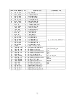
Page 76: ...TAINING BRKT HORIZ PTV 101 838 13145 02 10 LED BD GUN SENSE HOD 201 050 U00300 20 M3 NUT NYLOK PAS 101 20 202 068 330808 PN 20 M3 WSHR 8OD FLT NYLON 101 20 203 050 F00400 1 M4 NUT FLG SER PAS EARTH 1...

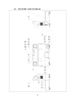
Page 77: ...74 8 5 SPX 1000UK ASSY PTV CABI DX...

Page 78: ...STICKER CABI F R 32 SPX 1008UK 1 STICKER CABI TOP L 33 SPX 1009UK 1 STICKER CABI TOP R See DESIGN RELATED PARTS 101 354081 5 TWIST LOK BHKL 450 4 102 280 A00964 WX 4 ROUTER TWIST D09 SO6 4 201 000 T00...

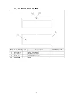
Page 79: ...76 8 6 SPX 1060UK ASSY LID UPPER ITEM PART NUMBER QTY DESCRIPTION COMPONENT REF 1 HOD 1051 A 1 FRONT LID U BLANK 2 SPX 1061UK 1 STICKER LID UPPER 3 TH1015UK 1 LOCKING TONGUE UK 101 220 5575UK 1 LOCK...

Page 80: ...PART NUMBER QTY DESCRIPTION COMPONENT REFERENCE 1 HOD 1061 AUK 1 FRONT LID L BLANK 2 HOD 1062 A 1 FRONT LID BRKT BLANK 3 SPX 1071UK 1 STICKER LID LOWER 201 050 F00400 3 M4 NUT FLG SER PAS 2 3 202 060...

Page 81: ...PT 3101 2 TUBE CLAMP 12 MAZ 2100 2 CONTROL UNIT NOT SHOWN 14 HOD 1304 1 JOINT PART LID 18 DUT 0302UK 1 COIN PATH PLATE 25 SPY 1106 2 HOLDER BRKT 26 HOD 1307 A 1 SIDE BRKT L BLANK 27 HOD 1308 A 1 SIDE...

Page 82: ...LT W S BLK 25 8 26 27 4 209 030 000616 SB 8 M6X16 BLT W S BLK 2 8 210 060 F00600 0B 8 M6 WSHR FORM A FLT BLK 2 8 211 000 P00408 W 2 M4X8 MSCR PAN W FS PAS EARTHS 2 212 008 T00408 0C 4 M4X8 TMP PRF TH...

Page 83: ...FERENCE 1 HOD 1351 1 PIPE L 2 SPX 1151UK 1 STICKER FENCE L 3 HOD 0004UK 2 PLATE HOLDER 101 601 6076 OBUK 1 LEG ADJUSTER 32MM BLACK 201 000 T00412 0B 8 M4X12 MSCR TH BLK 2 6 3 2 202 068 441616 0B 8 M4...

Page 84: ...FERENCE 1 HOD 1361 1 PIPE R 2 SPX 1161UK 1 STICKER FENCE R 4 HOD 0004UK 2 PLATE HOLDER 101 601 6076 OBUK 1 LEG ADJUSTER 32MM BLACK 201 000 T00412 0B 8 M4X12 MSCR TH BLK 2 6 3 2 202 068 441616 0B 8 M4...

Page 85: ...SPX 2000UK ASSY CTRL PANEL DX ITEM PART NUMBER QTY DESCRIPTION COMPONENT REFERENCE 1 MAZ 2001 A W 1 CTRL PNL BLANK W NUT PLATES 101 509 5712 01S 2 SW PB W L 6V YELLOW 301 HOD 60020 1 WIRE HARN CONTRO...

Page 86: ...PLEASE RECYCLE 101 400 5397 01 1 SW REGU FOR JVS VA 102 837 13551 92 1 I O CONTROL BD FOR JVS 103 838 13616 1 AUDIO POWER AMP 2CH 104 280 A00964 WX 7 ROUTER TWIST D09 SO6 4 WOOD X 105 354081 6 TWIST L...

Page 87: ...60005 1 WIRE HARN AUDIO L 308 SPY 60006 1 WIRE HARN AUDIO R 309 SPY 60007UK 1 WIRE HARN SW CONTROL 310 600 7009 2500 1 ASSY RGB CA D SUB 15P 2500MM 313 600 7141 100 1 CABLE JVS TYPE A B 100CM 315 600...

Page 88: ...8 WRAP BUBBLE SM 201 030 000850 SB 4 M8X50 BLT W S BLK FENCE L R 2EA 202 030 000830 SB 8 M8X30 BLT W S BLK FENCE L R 4EA 203 029 F00625 0B 4 M6X25 SKT CSK BLK 205 000 T00420 0B 4 M4X20 MSCR TH BLK FEN...

Page 89: ...T FUSED 1OA 250Vac 106 514 5078 5000 1 FUSE 5X20 CERAMIC SB 5000mA 107 310 5029 D508 0 04 HEAT SHRINK SLEEVING 50 8DIA 109 421 6595 5000 T 1 STICKER FUSE 5000mA TYPE T 201 000 P00308 4 M3X8 MSCR POSI...

Page 90: ...BOX 201 000 P00512 W 2 M5X12 MSCR POSI PAN W FS PAS 101 2 301 HOD 60025 1 WIRE HARN SPEAKER UNIT 8 17 HOD 1530 ASSY FAN UNIT ITEM PART NO QTY DESCRIPTION COMPONENT REF 1 105 5340 01 2 FAN BRKT LONG 1...

Page 91: ...he wire will be of a single colour shown by the left hand side numeral see the list above Note 1 If the right hand side alphanumeric is not 0 that particular wire has a spiral colour code The left han...

Page 92: ...LOCATE A3 SCHEMATIC DRAWING 1 HERE...

Page 93: ...LOCATE A3 SCHEMATIC DRAWING 2 HERE...

Page 94: ...SEGA AMUSEMENTS EUROPE LTD SEGA SERVICE CENTRE Suite 3a Oaks House 12 22 West Street Epsom Surrey United Kingdom KT18 7RG Telephone 44 0 1372 731820 Fax 44 0 1372 731849 SEGA 2002...

Reviews: