background image


63 


20 .    MENU & CODE   


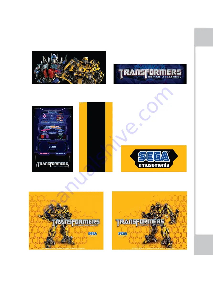
For the warning display sticker, please refer to section 1. 


STS-F00580 -


Billboard image

                                      STS-F00590 - Lamp box

 image


STS-F00620 -

 Instruction

            STS-F00600 -

 front gate image

                STS-F00610-SEGA LOGO 


STS-F00630- 

IMAGE Left

                                                            STS-F00640-

IMAGE Right


20 

 M

EN
U

 &

 C

O

D

E


http://op.sega.jp/op_e/

Summary of Contents for Transformers Human Alliance

Page 1: ...PMA B00590 PMA B00590 OWNER S MANUAL TRANSFORMERS PRINTING http op sega jp op_e...

Page 2: ...t to the following conditions The above copyright notice and this permission notice shall be included in all copies or substantial portions of the Software THE SOFTWARE IS PROVIDED AS IS WITHOUT WARRA...

Page 3: ...icense and or sell copies of the Software and to permit persons to whom the Software is furnished to do so subject to the following conditions The above copyright notice and this permission notice sha...

Page 4: ...to Indicates a protective earth terminal Before operating the equipment be sure to connect it to the ground The step may be omitted for products in which a power cable with earth is used Perform work...

Page 5: ...nted instructions describing potentially hazardous situations are applied to places where accidents can be caused Ensure that where the product is operated has sufficient lighting allowing the warning...

Page 6: ...dented portions or defects cuts etc on the external surfaces of the cabinet Are casters and adjusters damaged Do the power supply voltage and frequency requirements meet with those of the location Ar...

Page 7: ...VI http op sega jp op_e...

Page 8: ...ANCE FOR CONTROLLER PART 42 11 1 Repair and maintenance for motor 42 11 2 Repair and maintenance for controller handle infrared 42 11 3 Repair and maintenance for mobile potentiometer left and right 4...

Page 9: ...s housing 54 18 COMMON TROUBLESHOOTING 55 18 1 Start the game the aim point in the screen cannot be movable when swinging the controller left and right 55 18 2 Start the game the aim point in the scre...

Page 10: ...1 1 SPECIFICATIONS DIMENSION 1630 1370 2600 mm WEIGHT 208KG POWER 340W CURRENT 1 54A VOLTAGE 220V 50HZ HK 110V 50HZ TW 1 SPECIFICATIONS http op sega jp op_e...

Page 11: ...t equipment vending machine assembly maintenance inspection and replacement of units expendable parts Other qualified professionals Persons employed by amusement equipment manufacturers or involved in...

Page 12: ...3 2 WARNING LABELS DRAWINGS WARNING LABELS POSITION 2 WARNING LABELS DRAWINGS WARNING LABELS POSITION http op sega jp op_e...

Page 13: ...4 3 GAME MACHINE INSTALLATION LOCATION 3 GAME MACHINE INSTALLATION LOCATION http op sega jp op_e...

Page 14: ...5 4 DIMENSION 4 DIMENSION http op sega jp op_e...

Page 15: ...BILLBOARD LAMP THE LEFT SIDE THE RIGHT SIDE RIGHT SPEAKER 55 LCD 1P CONTROLLER LEFT SPEAKER COIN SELECTOR 2P CONTROLLER 1P START BUTTON 2P START BUTTON LCD BACKSIDE POWERBOX SERVICE DOOR MAINFRAME 5 P...

Page 16: ...or coin box door upper x919 2 PMA B00090 Key for coin box door lower and others 2 Shipment after the demolition of packaging components DTRF S02300 Billboard Lamp fixed plate 2 DTRF H00100 DTRF S00100...

Page 17: ...cation of the parts POP Billboard Assembly Metal for fixed Billboard and screws 2pcs for each Fuse 1pcs AC power cord 1pcs all the above parts sort out into the coin box keys are bound on the left sid...

Page 18: ...lon the Billboard The 2 pcs of metal put in the coin box locked false by 4 pcs of screws locked false on the Billboard Locked false by 2 pcs of screws Locked false on the machine Locked tightly by 2...

Page 19: ...t and right of LCD 4 Install host computer 5 Host computer wire connection Please pay more attention to the direction of the pictures Locked tightly by 4 pcs of screws locked false on the machine 7 IN...

Page 20: ...and Hex Socket M8 M5 7 3 INSTALL THE BILLBOARD LAMP Leg Adjuster Castors Castors Leg Adjuster Leg Adjuster Castors Castors Leg Adjuster Adjust from 7 to ON Connect to COM1 Connect to DVD 7 INSTALLATIO...

Page 21: ...s be stable Do not expose the power cable or earth wire If these are exposed customers could stumble over them for instance and easily damage them Additionally if these lines are damaged there could b...

Page 22: ...rd connector on the side opposite the power plug into the AC unit inlet Fully insert the power cord plug into the outlet The power cord is laid out indoors Protect the power cord by attaching wire cov...

Page 23: ...billboard plate 2 Unplug the right lamp wire connector 3 Disassemble the left side billboard plate Unscrew 3pcs of M4 25 cross flat head screws with 3mm hexagonal key Steady the side plate to prevent...

Page 24: ...he lamp power supply cord from the LCD lamp wire connector 6 Disassemble the billboard Unscrew 6pcs of M4 25 round cup screws with cross screwdriver and remove the display door LCD lamp wire connector...

Page 25: ...damage when moving the machine Unscrew 2pcs of screws with cross screwdriver Unscrew 2pcs of M8 35 screws with 6mm hexagonal key Caution The work of disassembling for the billboard needs at least two...

Page 26: ...system internal counter Based on the difference of test mode settings INSERT COIN S INSERT MORE COIN S may change to SWIPE CARD TO PLAY The player s acting role based on which side the START button is...

Page 27: ...enemies in the game If some enemies appear to be outlined this is the signal to attack Please rotate the controller and pull the trigger aim and destroy it before it hurts you BASIC CONTROL 9 GAME IN...

Page 28: ...you the player s life gauge will decrease If the player s life gauge decreases to 0 the game is over When the crosshair of player1 and player2 are close to each other allied Autobots will show their...

Page 29: ...ts will attack enemies with player s fire By destroying enemies by Autobots fire the alliance fire and times of alliance fire will display in the screen center By destroying enemies by Autobots fire t...

Page 30: ...special enemies carrying energon cubes These enemies will have blue shinning After this type of enemies are destroyed companied Autobots will gain their energon cubes SUPER ALLIANCE FIRE 9 GAME INTRO...

Page 31: ...t as the alliance fire to provide more powerful fire for the players Super alliance fire will be triggered in single mode as well As game plays along players will fight together with Autobots to again...

Page 32: ...isappear This round attack from Deceptions will be resolved and players will be rewarded extra bonuses If the players can t clear all the attack marks before they disappear the players will be attacke...

Page 33: ...24 Based on the damage of the marker diverse result will appear Based on players performances in co op game the final result screen will be differed 9 GAME INTRODUCTION http op sega jp op_e...

Page 34: ...the mini game called ACTION SEQUENCE CONTROLS will take place Players have to turn laser controller directions or press the button on screen information ACTION SEQUENCE CONTROLS 9 GAME INTRODUCTION ht...

Page 35: ...26 If the players succeed in action they can avoid Decepticons attack and gain extra score bonus If the players fail in action life gauge will be decreased 9 GAME INTRODUCTION http op sega jp op_e...

Page 36: ...ht against Just like in co op mode there will be attack markers on these BOSSES Destroy them before attack markers disappear the BOSS life gauge will decrease When the BOSS life gauge decreases to 0 i...

Page 37: ...e BOSS captures Bumblebee and the players successfully destroy all the attack markers Bumblebee will be rescued and the Friendship between you two will rise When each level is cleared Stage Result wil...

Page 38: ...sert coins and press START button If enough credits are reached the START button on the other side on cabin will continue flick press to join the game When the player s life gauge is 0 Continue Game s...

Page 39: ...ch SOUND VOLUME Adjust sound volume for all of the machines speakers Coin Counter Counts and displayes coins in 0 10 units Coin Counter 1 Test Button Service Button Sound Volume Switch WARNING Never t...

Page 40: ...u Item BOOKKEEPING Displays all recorded game data INPUT TEST Tests each input device used for the game OUTPUT TEST Tests each output device used for the game GAME ASSIGNMENTS Adjusts all game setting...

Page 41: ...COIN1 Number of coins inserted in coin chute 1 COIN2 Number of coins inserted in coin chute 2 TOTAL COINS Total Number of coins inserted in coin chute COIN CREDITS Number of credits for coins inserted...

Page 42: ...tal number of first time plays by Player 1 and Player 2 CONTINUE PLAY Total number of times Player 1 and Player 2 opted to continue TOTAL TIME Amount of time the cabinet has been in operation PLAY TIM...

Page 43: ...the TEST Button to return to GAME TEST MODE screen Menu Item Play time will be recorded into different lines by 30 seconds intervals All play times over 10 minutes are written into the line OVER 10M00...

Page 44: ...will display OFF PLAYER1 START BUTTON Press the Player 1 START button the item will display ON release the button the item will display OFF PLAYER2 CONTROLLER X Move the Player 2 right side controlle...

Page 45: ...ller is on PLAYER2 BRAKE LAMP Player 2 red brake lamp at the base of the controller is on BILLBOARD LAMP 2 lamps at the 2 ends of the light box above the screen are on EMBLEM LAMP The lamp at the cent...

Page 46: ...F they will If the setting is ON they will not ON is set by default PLAYER1 CONTROLLER REACTION Set if Player 1 left side controller will vibrate when shooting ON is set by default PLAYER2 CONTROLLER...

Page 47: ...E Button to move the cursor to the desired test item Press the TEST Button to confirm selection of the item Select EXIT and press the TEST Button to return to the GAME TEST MODE screen Check Method Re...

Page 48: ...Player 1 s controller to top left corner extreme position and press the trigger Then in turn rotate to top right corner bottom left corner and bottom right corner extreme position and press the trigge...

Page 49: ...LIBRATION SETTING 2 Select DEFAULT SETTING in CONTROLLER CALIBRATION SETTING screen and press test button to go to DEFAULT SETTING screen COMPLETED will be displayed to indicate the controller calibra...

Page 50: ...button to select menu item Select YES CLEAR and press TEST button to clear all backup data When COMPLETED is displayed press TEST button again and return to GAME TEST MODE screen Select NO CANCEL and...

Page 51: ...rared Unscrew 8PCS of M4 12 with 2 5mm hexagonal key Start the game put an opaque object into the infrared detector grooves and check whether the infrared detector is workable Always keep the infrared...

Page 52: ...sleeve Test the Potentiometer with multimeter and the normal value should be between 0 5K Regularly clean the gear and add lubricating oil so as to keep the gear running smoothly Test the Potentiomete...

Page 53: ...ve the STAR BUTTON PLATE 12 2 Remove the micro switch from the lamp housing Check Regularly whether the connector is fixed and LED in good condition please fix it if there is any problem with them Uns...

Page 54: ...OR OTHER COMPONENTS 13 1 Repair and maintenance for the brake light panel 1 Unscrew the screws arrow with 2 5mm hexagonal key 2 Disassemble the lamp panel replace the bad LCD lamp bead after power on...

Page 55: ...ontrol table lamp 1 Unscrew the screws red arrow with 2 5mm hexagonal key Pull out the cover gently 3PCS M4 25 wire connector 55 cover edge long RGB lamp bar 55 billboard base plate billboard plate mo...

Page 56: ...s red arrow with cross screw driver b LED_5050 PCB V3 1 Unplug the wire connector and replace the lamp bar LED_5050 PCB V3 1 c Follow the original order when installing the red insulating spacer and t...

Page 57: ...14 GRAPHICS DISPLAY 14 1 LCD component 14 2 Button Names and Functions LCD power supply LCD driver board power connector Control Panel VGA connector 55 LCD screen 14 GRAPHICS DISPLAY http op sega jp o...

Page 58: ...Coin Selector should be cleaned once every 3 months please follow the below procedure When cleaning the Coin Selector 1 Turn off the machine power first and then open the coin chute gate 2 Remove the...

Page 59: ...ng the REJECT Button pressed down Are extra coins and incorrect coins properly returned 16 HOW TO REPLACE THE PANEL LIGHTING TUBE FOR BILLBOARD 16 1 Replace the lamp box lighting tube 1 Disassemble th...

Page 60: ...mble the plastic cover of the lamp box Unscrew the 8PCS of M4 30 with 2 5mm hexagonal key Unplug the lighting tube wire connector Cut the cable ties Wire connector of Controller head lamp panel 16 HOW...

Page 61: ...the lamp panel Replace the lighting tube T4 220V 22W L 700mm The muzzle lamp panel support plastic nuts PCB lamp panel The muzzle scatter plate Controller head cover 16 HOW TO REPLACE THE PANEL LIGHT...

Page 62: ...ng is gained by first removing the Start Button Plate 17 2 Remove the Button Plate from the Control Panel to gain access to the Switch and Lamp housing Start switch and lamp housing Unscrew 8PCS of M4...

Page 63: ...nger and thumb gently remove the housing from the button cover Always hold firmly onto the housing but not the wires and remove the lamp from the lamp housing The Lamp is a push fit and should not be...

Page 64: ...the M4 8 red arrow and replace the middle potentiometer 3 Installation of the middle potentiometer should read the following figure as reference Adjustment in details please refer to 10 2 6 the middl...

Page 65: ...n 11 2 Disassemble the controller side cover 3 Unscrew the M4 8 red arrow and replace the middle potentiometer 4 Flat side of potentiometer and angle of controller body s horizontal plane is about 75...

Page 66: ...tronics devices on the IC board before handling the IC board touch a grounded metallic surface so that the static electricity can be discharged WARNING When returning the game board after making repai...

Page 67: ...ixing Points 4 CAUTION Do not open the Game Board without the express permission of SEGA If for any reason entry has been gained into the Game Board without the permission of SEGA then all warranty ri...

Page 68: ...etal filter The screws are on the reverse side from the connector side Clean around the air vent of the RINGEDGE2 with a vacuum cleaner IMPORTANT You should clean the RINGEDGE2 once pe r year or when...

Page 69: ...in the figure below DIP SW IMPORTANT Use with the dip switches DIP SW on the board at the prescribed settings If settings do not match the product an error message will be displayed In some cases the...

Page 70: ...product purchase location IMPORTANT When the following error code or information is displayed please reference RINGEDGE2 service booklet If no record can be found in RINGEDGE2 service booklet please t...

Page 71: ...the game spec Reason The I O board is not correctly used Solution Please use JVS I O board which fulfills the game spec PROGRAM SPECIFIC Display Error 1000 Wrong Coin Setting Reason Coin setting is i...

Page 72: ...sticker please refer to section 1 STS F00580 Billboard image STS F00590 Lamp box image STS F00620 Instruction STS F00600 front gate image STS F00610 SEGA LOGO STS F00630 IMAGE Left STS F00640 IMAGE R...

Page 73: ...64 21 PARTS LIST 21 PARTS LIST http op sega jp op_e...

Page 74: ...0500 55 controller stand assemblies 1 6 TRF 55 0600 LCD wood Shell 1 7 TRF 55 0700 LCD assemblies 1 8 TRF 55 0800 left side of billboard plate 1 9 TRF 55 0900 right side of billboard plate 1 10 TRF 55...

Page 75: ...rce box assemblies 1 3 TRF 55 0100 S03 coin selector assemblies 1 4 TRF 55 0100 S04 base control plate assemblies 1 5 TRF 55 0100 S05 test service button assemblies 1 21 3 Control board cover assembli...

Page 76: ...5 0300 NO PARTNUMBER DESCRIPITION QTY 1 DTRF P00600 controller stand front cover Left 1 2 DTRF H00500 controller stand back lamp plane 1 21 5 front cover Right for controller stand TRF 55 0400 NO PART...

Page 77: ...block panel 2 3 DTRF S02000 base block panel 1 4 DTRF S01900 lamp panel supporting frame 2 5 ELE F00820 PCB 2 6 DTRF H00700 controller stand light filter plate 2 21 7 LCD wood Shell TRF 55 0600 NO PA...

Page 78: ...glass Fixed plate4 2 6 TRF 55 0700 S02 glass Fixed plate3 2 21 9 The left side billboard plate TRF 55 0800 NO PARTNUMBER DESCRIPITION QTY 1 D55 TRF S00100 55 cover edge 1 2 ELE F00860 Long RGB light...

Page 79: ...D55 TRF H001R00 55 right side of billboard plate 1 5 D55 TRF S00200 55 side billboard plate back plate 1 21 11 Lighting box assemblies TRF 55 1000 NO PARTNUMBER DESCRIPITION QTY 1 TRF 55 1010 Billboa...

Page 80: ...71 21 12 controller assemblies TRF GUN 0000 21 13 control board wood block TRF 55 1100 21 14 base box back gate TRF 55 1200 21 15 base box side gate TRF 55 1300 21 PARTS LIST http op sega jp op_e...

Page 81: ...72 22 SCHEMATIC DIAGRAM 22 SCHEMATIC DIAGRAM http op sega jp op_e...

Page 82: ...73 22 SCHEMATIC DIAGRAM http op sega jp op_e...

Page 83: ...74 22 SCHEMATIC DIAGRAM http op sega jp op_e...

Page 84: ...75 22 SCHEMATIC DIAGRAM http op sega jp op_e...

Reviews: