CYLINDER HEAD, CYLINDER, PISTON
CYLINDER HEAD, CYLINDER, PISTON
3-5-22
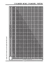
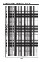
Optional tappet specifi cations
Part number F01A20007-
001
002
003
004
005
006
007
008
009
010
3 digits
480
482
484
486
488
490
492
494
496
498
Part number F01A20007-
011
012
013
014
015
016
017
018
019
020
3 digits
500
502
504
506
508
510
512
514
516
518
Part number F01A20007-
021
022
023
024
025
026
027
028
029
030
3 digits
520
522
524
526
528
530
532
534
536
538
Part number F01A20007-
031
032
033
034
035
036
037
038
039
040
3 digits
540
542
544
546
548
550
552
554
556
558
Part number F01A20007-
041
042
043
044
045
046
047
048
049
050
3 digits
560
562
564
566
568
570
572
574
576
578
TIPS
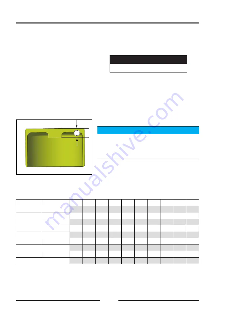
Valve clearance specifications and measured valve
clearance are calculated in millimeters (mm). A 480
tappet means that the center thickness of the tappet
【
A
】
is 4.80mm.
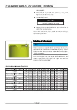
Selection of valve tappet
Selection of valve tappet
A
A
The valve tappet part number is F01A20007XXX, and
"XXX" corresponds to the specifi ed tappet thickness. As
shown in the following table:
are adjusted.
◆
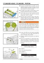
Reinstall the camshaft and camshaft cover, and
tighten the bolts as required.
◆
Tightening torque:
Bolt (M6)
9.8 N•m (1.0kgf•m, 87in•lb)
◆
Measure and confirm that each valve clearance is
within the required range.
If the valve clearance is not within the required range,
repeat this procedure.
Summary of Contents for S301000-20100A
Page 1: ...SERVICE MANUAL SSV 4 3 4 130 6 54...
Page 50: ...ENGINE LUBRICATION SYSTEM 3 1 2 Exploded view...
Page 63: ...EFI SYSTEM 3 2 2 Exploded view Exploded view...
Page 67: ...STARTING SYSTEM 3 3 2 Exploded view...
Page 75: ...CRANKCASE CRANKSHAFT BALANCE SHAFT 3 4 2 Explosive view...
Page 76: ...CRANKCASE CRANKSHAFT BALANCE SHAFT 3 4 3 Explosive view of Up and down the case sub assembly...
Page 100: ...CYLINDER HEAD CYLINDER PISTON CYLINDER HEAD CYLINDER PISTON 3 5 3 Exploded view...
Page 141: ...CVT SYSTEM 3 6 2 Exploded view...
Page 151: ...WATER PUMP ASSEMBLY 3 7 2 Exploded view...
Page 197: ...6 6 COOLING SYSTEM SPECIAL TOOLS AND SEALANTS Silicone Sealant Special tools and sealants...
Page 227: ...9 2 FRONT REAR SUSPENSION EXPLODED VIEW OF FRONT SUSPENSION...
Page 229: ...9 4 FRONT REAR SUSPENSION EXPLODED VIEW OF REAR SUSPENSION...
Page 247: ...10 5 WHEELS AND TIRES SPECIAL TOOLS Jack...
Page 261: ...11 4 BRAKE SYSTEM SPECIAL TOOLS Inside Circlip Pliers...
Page 314: ...14 4 ELECTRICAL SYSTEM EXPLODED VIEW...
Page 407: ...14 97 ELECTRICAL SYSTEM ELECTRIC SCHEMATIC DIAGRAM...


