CYLINDER HEAD, CYLINDER, PISTON
CYLINDER HEAD, CYLINDER, PISTON
3-5-28
H
H
II
JJ
K
K
LL
N
N
M
M
P
P
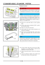
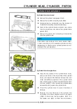
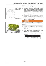
Remove the valve
!
WARNING
When disassembling and assembling the cylinder head
or operating the valve spring, you need to wear goggles.
TIPS
In order to ensure that the parts can be installed back to
the original position, the matching parts should be put
together and arranged according to their position on the
cylinder head. The removed parts should be marked or
placed on an arranged shelf.
◆
Remove the valve lifter
【
G
】
from the cylinder
head.
◆
Use the valve spring compressor
【
H
】
to press
down the valve spring.
◆
Remove the valve lock clamp
【
I
】
.
◆
Slowly release the valve spring compressor and
remove the compressor.
◆
Remove the lock clamp seat
【
J
】
, valve spring
【
K
】
, valve spring seat
【
L
】
and valve oil seal
【
M
】
.
TIPS
As long as the cylinder head is disassembled, the valve
oil seal is replaced. Aging, cracking or abrasion of the
valve oil seal will lead to increased oil consumption
◆
Lift the cylinder head, take out the valve
【
N
】
,
and place it in an orderly manner so that it can be
reinstalled in the same valve guide.
◆
Repeat the previous steps to remove the remaining
valves.
◆
Clean the combustion chamber of the cylinder head
and the bottom surface of the cylinder head.
G
G
Summary of Contents for S301000-20100A
Page 1: ...SERVICE MANUAL SSV 4 3 4 130 6 54...
Page 50: ...ENGINE LUBRICATION SYSTEM 3 1 2 Exploded view...
Page 63: ...EFI SYSTEM 3 2 2 Exploded view Exploded view...
Page 67: ...STARTING SYSTEM 3 3 2 Exploded view...
Page 75: ...CRANKCASE CRANKSHAFT BALANCE SHAFT 3 4 2 Explosive view...
Page 76: ...CRANKCASE CRANKSHAFT BALANCE SHAFT 3 4 3 Explosive view of Up and down the case sub assembly...
Page 100: ...CYLINDER HEAD CYLINDER PISTON CYLINDER HEAD CYLINDER PISTON 3 5 3 Exploded view...
Page 141: ...CVT SYSTEM 3 6 2 Exploded view...
Page 151: ...WATER PUMP ASSEMBLY 3 7 2 Exploded view...
Page 197: ...6 6 COOLING SYSTEM SPECIAL TOOLS AND SEALANTS Silicone Sealant Special tools and sealants...
Page 227: ...9 2 FRONT REAR SUSPENSION EXPLODED VIEW OF FRONT SUSPENSION...
Page 229: ...9 4 FRONT REAR SUSPENSION EXPLODED VIEW OF REAR SUSPENSION...
Page 247: ...10 5 WHEELS AND TIRES SPECIAL TOOLS Jack...
Page 261: ...11 4 BRAKE SYSTEM SPECIAL TOOLS Inside Circlip Pliers...
Page 314: ...14 4 ELECTRICAL SYSTEM EXPLODED VIEW...
Page 407: ...14 97 ELECTRICAL SYSTEM ELECTRIC SCHEMATIC DIAGRAM...


