CYLINDER HEAD, CYLINDER, PISTON
CYLINDER HEAD, CYLINDER, PISTON
3-5-31
JJ
F
F
E
E
D
D
G
G
H
H
A
A
B
B
C
C
Seat ring repair
◆
S e a t r i n g r e p a i r s h o u l d b e c a r r i e d o u t b y
professionals who are proficient in cylinder head
repair technology. Repair techniques vary, so please
follow the valve repair equipment manufacturer's
instructions. Do not over-grind the seat ring.
!
WARNING
When disassembling and reassembling the cylinder
head, wear goggles or face shield.
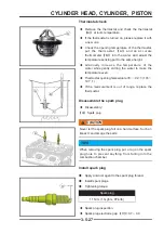
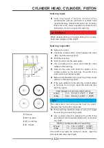
Seat ring inspection
◆
Remove the valve.
◆
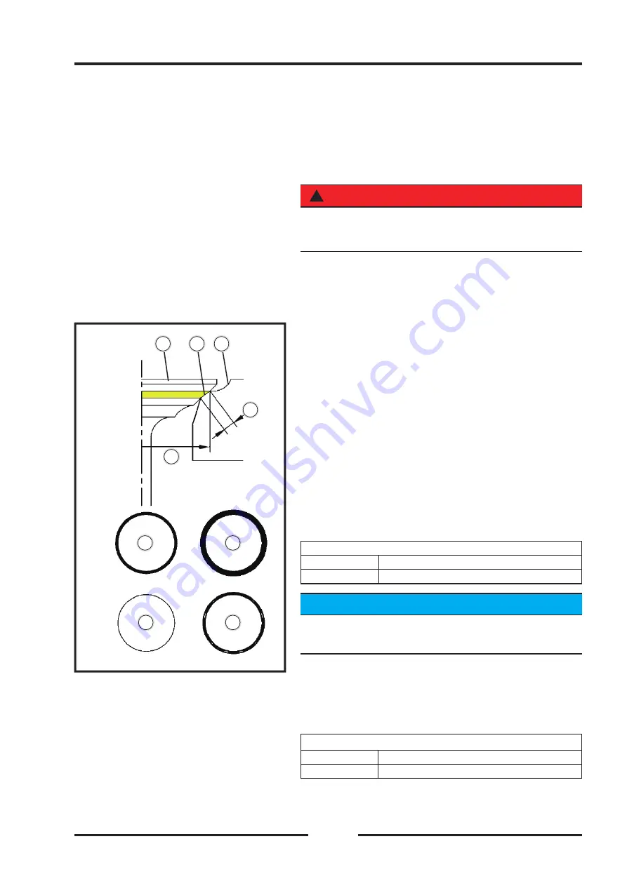
Check the contact surface
【
A
】
between the valve
【
B
】
and the seat ring
【
C
】
.
◆
Paint the seat ring.
◆
Push the valve into the valve guide.
◆
Use a grinding tool to press and rotate the valve
relative to the seat ring.
◆
Take out the valve and check the pattern of the
contact surface on the seat ring. The width of the
entire circle must be appropriate.
◆
Measure the diameter of the outer ring of the contact
surface on the seat ring
【
D
】
.
◆
If the outer diameter of the seat ring contact surface
is too large or too small, repair the seat ring (see
seat ring repair).
Outer diameter of seat ring contact surface
exhaust
31.8 ~ 31.9mm (1.2520" ~ 1.2559")
intake
36.8 ~ 36.9mm (1.4488" ~ 1.4528")
TIPS
The valve stem and valve guide must be good,
otherwise the check will be inaccurate.
◆
If the seat ring interface shape is not good, repair
the seat ring (see seat ring repair).
◆
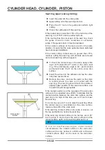
Use a vernier caliper to measure the width of the
part without carbon deposits (bright part) on the seat
ring
【
E
】
.
Width of contact surface of seat ring
Exhaust
1.5 ~ 1.6mm (0.0591" ~ 0.0630")
intake
1.0 ~ 1.1mm (0.0394" ~ 0.0433")
If the width is too wide, too narrow or uneven, repair the
valve seat (see valve seat repair)
【
F
】
Good
【
G
】
Too wide
【
H
】
too narrow
【
J
】
Uneven
Summary of Contents for S301000-20100A
Page 1: ...SERVICE MANUAL SSV 4 3 4 130 6 54...
Page 50: ...ENGINE LUBRICATION SYSTEM 3 1 2 Exploded view...
Page 63: ...EFI SYSTEM 3 2 2 Exploded view Exploded view...
Page 67: ...STARTING SYSTEM 3 3 2 Exploded view...
Page 75: ...CRANKCASE CRANKSHAFT BALANCE SHAFT 3 4 2 Explosive view...
Page 76: ...CRANKCASE CRANKSHAFT BALANCE SHAFT 3 4 3 Explosive view of Up and down the case sub assembly...
Page 100: ...CYLINDER HEAD CYLINDER PISTON CYLINDER HEAD CYLINDER PISTON 3 5 3 Exploded view...
Page 141: ...CVT SYSTEM 3 6 2 Exploded view...
Page 151: ...WATER PUMP ASSEMBLY 3 7 2 Exploded view...
Page 197: ...6 6 COOLING SYSTEM SPECIAL TOOLS AND SEALANTS Silicone Sealant Special tools and sealants...
Page 227: ...9 2 FRONT REAR SUSPENSION EXPLODED VIEW OF FRONT SUSPENSION...
Page 229: ...9 4 FRONT REAR SUSPENSION EXPLODED VIEW OF REAR SUSPENSION...
Page 247: ...10 5 WHEELS AND TIRES SPECIAL TOOLS Jack...
Page 261: ...11 4 BRAKE SYSTEM SPECIAL TOOLS Inside Circlip Pliers...
Page 314: ...14 4 ELECTRICAL SYSTEM EXPLODED VIEW...
Page 407: ...14 97 ELECTRICAL SYSTEM ELECTRIC SCHEMATIC DIAGRAM...


