8-
15
DRIVE SYSTEM
◆
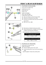
First install the small clamp, adjust the position of
the dust cover to ensure that the dust cover is stuck
in the groove of the intermediate shaft, and then use
clamp pliers to clamp the small clamp
◆
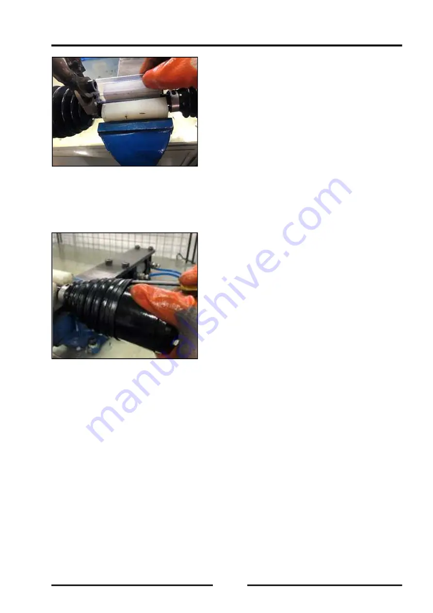
When installing the large clamp, first clip the dust
cover into the groove of the universal joint, and then
exhaust the gas in the dust cover. Use a screwdriver
to lift up a corner of the dust cover, being careful not
to puncture the dust cover, and then go back and
forth. Push and pull the universal joint, you can hear
the sound of gas fl owing, stay the universal joint in
the middle position, take out the screwdriver and
clamp the big clamp
◆
Wipe clean the grease on the universal joint and the
intermediate shaft and then use it
◆
The above maintenance procedures are applicable
to the inner ball cage of the front drive shaft
Summary of Contents for S301000-20100A
Page 1: ...SERVICE MANUAL SSV 4 3 4 130 6 54...
Page 50: ...ENGINE LUBRICATION SYSTEM 3 1 2 Exploded view...
Page 63: ...EFI SYSTEM 3 2 2 Exploded view Exploded view...
Page 67: ...STARTING SYSTEM 3 3 2 Exploded view...
Page 75: ...CRANKCASE CRANKSHAFT BALANCE SHAFT 3 4 2 Explosive view...
Page 76: ...CRANKCASE CRANKSHAFT BALANCE SHAFT 3 4 3 Explosive view of Up and down the case sub assembly...
Page 100: ...CYLINDER HEAD CYLINDER PISTON CYLINDER HEAD CYLINDER PISTON 3 5 3 Exploded view...
Page 141: ...CVT SYSTEM 3 6 2 Exploded view...
Page 151: ...WATER PUMP ASSEMBLY 3 7 2 Exploded view...
Page 197: ...6 6 COOLING SYSTEM SPECIAL TOOLS AND SEALANTS Silicone Sealant Special tools and sealants...
Page 227: ...9 2 FRONT REAR SUSPENSION EXPLODED VIEW OF FRONT SUSPENSION...
Page 229: ...9 4 FRONT REAR SUSPENSION EXPLODED VIEW OF REAR SUSPENSION...
Page 247: ...10 5 WHEELS AND TIRES SPECIAL TOOLS Jack...
Page 261: ...11 4 BRAKE SYSTEM SPECIAL TOOLS Inside Circlip Pliers...
Page 314: ...14 4 ELECTRICAL SYSTEM EXPLODED VIEW...
Page 407: ...14 97 ELECTRICAL SYSTEM ELECTRIC SCHEMATIC DIAGRAM...


