background image

9 -


16

FRONT & REAR SUSPENSION


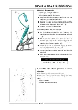
The rocker maintenance  


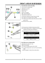
Add grease  


When it  is found  that  the lubricating  grease in the 
shaft sleeve of the suspension rocker arm and the 
bearing sleeve of the wheel axle is reduced, or every 
1000Km  of  the  vehicle,  it  is  necessary  to  fill  the 
grease through the butter nozzle in the suspension 
system 

A

 using the tool.  


Dedicated tool

 oiling gun  

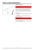
!

When  there is no proper lubrication for the suspension 
joints, it needs to be fi lled with grease and maintained
regularly to avoid excessive wear of shaft sleeve.

A

A

B

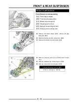
Hub bearing replacement

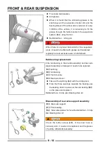
If the hub bearing in the knuckle assembly and rear axle 
support assembly is damaged, it needs to be replaced.

A

split ring

B

hub bearing

C

Front knuckle

D

Rear axle mount


Take out the split ring

A

with the circlip pliers


From the three openings opposite the bearing, use 
the bearing driver to press out the hub bearing

B

on the press and replace it

Dedicated tool

Circlip plier, Bearing drive kit

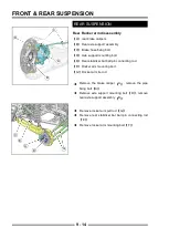
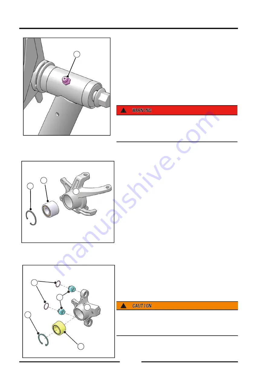
Disassembly of rear axle support assembly

E

 Rear axle support  

F

 Plain bearing  

G

 Steel wire retainer for hole  Dedicated tool

Circlip 

plier, Bearing drive kit

!

Check  the  buffer  sleeve

F

,  If  the  inner  hole  is 

seriously worn, it needs to be replaced, and the grease 
should be refi lled after assembly.


C

E

F

G

A

B

Summary of Contents for S301000-20100A

Page 1: ...SERVICE MANUAL SSV 4 3 4 130 6 54...

Page 2: ...FRONT AND REAR AXLE 4 1 4 1 FUEL SYSTEM 5 1 5 1 COOLING SYSTEM 6 1 6 1 INTAKE SYSTEM 7 1 7 1 DRIVE CHAIN SYSTEM 8 1 8 1 FRONT AND REAR SUSPENSION 9 1 9 1 RIM AND TIRE 10 1 10 1 BRAKE SYSTEM 11 1 11 1...

Page 3: ...nd forms 1 This manual is provided by Segway Technology Co Ltd and is prepared for qualified professional and technical personnel Attempts to repair and maintain the vehicle without proper training an...

Page 4: ...er degree s Celcius centrifugal variable Transmission direct current farad s degree s Fahrenheit foot feet gram s Kilograms per square centimeter hour s liter s lb m mm min N Nm Pa HP PS psi r rpm TDC...

Page 5: ...a potential hazard that may result in severe injury or death to the operator bystander or person s inspecting or servicing the vehicle CAUTION CAUTION CAUTION indicates a potential hazard that may re...

Page 6: ...1 1 GENERAL INFORMATION VEHICLE IDENTIFICATION NUMBER ENGINE SERIAL CODE 1 2 TECHNICAL PARAMETERS OF VEHICLE 1 3 UNIT CONVERSION TABLE 1 6 TORQUE 1 7 GENERAL INFORMATION...

Page 7: ...Number Meaning 1 3 1 3 Manufacturer s identi cation code Manufacturer s identi cation code 8 8 Designed sequence number Designed sequence number 4 4 Vehicle category Vehicle category 9 9 Check Number...

Page 8: ...T1a T1b 620mm Steering wheel diameter 310mm Carrying load 90 kg Reserve fuel volume 5L Rim type and speci cation Front wheel Aluminum rim1465 Anti drop aluminum rim1465 Rear wheel Aluminum rim1470 An...

Page 9: ...ompression ratio 12 0 1 Bore diameter mm stroke mm 93mm 73 6mm Starting method Electric start Ignition type Eletcricity ECU Spark plug type NGK CPR7EA TORCH B7RTC Spark plug clearance 0 7 0 9mm Lubric...

Page 10: ...Red 12 78 W Rear position light color speci cation Red 2 12 W Rear turn signal color speci cation Amber 2 32 W Color Speci cation of Rear License Plate Light White 2 5 W Battery capacity 12V 32Ah Shif...

Page 11: ...14 22 14 22 1 333 1 333 kPa kPa psi psi kPa kPa Power N N N N 0 1020 0 1020 0 2248 0 2248 kg kg lb lb kg kg kg kg 9 807 9 807 2 205 2 205 N N lb lb Volume L L L L L L L L L L L L mL mL mL mL mL mL 0...

Page 12: ...1 1 Bolt M12 1 25 185 M12 1 25 185 112 128 112 128 11 2 12 8 11 2 12 8 82 6 94 4 82 6 94 4 CVT Clutch primary CVT Clutch primary 2 2 Bolt M10 1 25 80 M10 1 25 80 75 85 75 85 7 5 8 5 7 5 8 5 55 3 62 7...

Page 13: ...ole 20 20 Shoulder bolt Shoulder bolt 10 14 10 14 1 0 1 4 1 0 1 4 7 10 7 10 4 Cylinder head 4 Cylinder head cover bolts cover bolts 21 21 Shoulder bolt Shoulder bolt 10 14 10 14 1 0 1 4 1 0 1 4 7 10 7...

Page 14: ...1 Front Suspension bolt Front Suspension bolt M12 1 25 145 M12 1 25 145 110 120 11 2 12 2 11 2 12 2 81 88 81 88 12 12 Front Suspension bolt Front Suspension bolt M12 1 25 65 M12 1 25 65 110 120 11 2 1...

Page 15: ...ting bolt Steering column mounting bolt M8 M8 20 26 20 26 2 0 2 6 2 0 2 6 14 7 19 14 7 19 L 28 28 Brake caliper body mounting bolt Brake caliper body mounting bolt M10 1 25 25 M10 1 25 25 40 40 50 50...

Page 16: ...Fuel System 2 11 Fuel Filter 2 11 Fuel Lines 2 12 Engine Intake Pre Filter Service 2 13 Air Filter Service 2 13 ENGINE 2 14 Engine Oil Level 2 14 Engine Oil Change 2 14 Replace oil lter oil strainer...

Page 17: ...25 Drive Shaft Boot Inspection 2 26 Wheel 2 26 Wheel Removal 2 27 Wheel Installation 2 27 ELECTRICAL AND IGNITION SYSTEM 2 28 Battery disassembly 2 28 Battery charging 2 28 ELECTRICAL AND IGNITION SY...

Page 18: ...ed dealer perform these operations Maintenance intervals in the following chart are based upon average riding conditions Vehicles subjected to severe use must be inspected and serviced more frequentl...

Page 19: ...en Headlight taillight worklight Daily Check operation apply dielectric grease if replacing lamps Air lter main element Weekly 3700 6000 Inspect replace as needed D Brake pad wear 10 H Monthly 100 160...

Page 20: ...pump replace lines every two years Radiator if applicable 100 H 12 M 1000 1600 Inspect clean external surfaces Cooling hoses if applicable 100 H 12 M 1000 1600 Inspect for leaks Engine mounts 100 H 1...

Page 21: ...Maintenance Schedule Engine Coolant 8 63 qts 9500 ml M a i n t a i n t h e l e v e l between the ll lines Refer to Maintenance Schedule Maintenance Reference Engine Oil Engine Coolant The oil level i...

Page 22: ...ntenance Schedule Front axle gear oil SAE 75 80W 90 GL5 0 16 qts 180 mL Maintain the fluid to the Fill Plug level Refer to Maintenance Schedule Rear axle gear oil SAE 75 80W 90 GL5 1 36 qts 1500 ml Ma...

Page 23: ...tion Method Schedule Front arm upper and lower Front balance bar Semi synthetic waterproof grease Grease ll MAX 2 pumps Per 2000 miles Rear balance bar Semi synthetic waterproof grease Grease ll MAX 2...

Page 24: ...l nuts and axle nuts check to be sure axle nuts are secured by cotter pins Engine Intake Pre Filter Inspect pre filter and clean with soapy water and compressed air if necessary PVT Intake Pre Filter...

Page 25: ...required loosen the lower jam nut and pull the cable out of the mount to move the upper jam nut A upper jam nut B lower jam nut Adjust the shift cable so there is the same amount of cable travel when...

Page 26: ...on loss of engine performance or high exhaust temperatures A Fuel Filter 1 B Fuel Filter 2 The fuel filter A is located behind the passenger seat and can be seen by removing the passenger seat and the...

Page 27: ...uel pipeline connected to the auxiliary fuel tank is worn deteriorated or damaged Replace the fuel line if necessary Locate the rear high pressure oil pipe connected to the engine under the cargo box...

Page 28: ...filter element of this vehicle is a paper air filter element The filter needs to be replaced after a period of use For details see the periodic maintenance table A Air lter cover snap B Air lter cove...

Page 29: ...ow the oil to ow back to the bottom of the engine Put a piece of cotton cloth under the end of the oil dipstick and then pull out the oil dipstick Wipe the oil dipstick clean Reinsert completely Put a...

Page 30: ...om of the vehicle A oil drain B O ring C oil plug D O ring E oil drain plug Discharge position 1 Put the vehicle on the horizontal surface Start the engine Let it heat up for two to three minutes whil...

Page 31: ...ace the shock absorber tilted back aside Unscrew the oil lter with a tool and pay attention to the direction of the screw when unscrewing Install a new lter and manually rotate it clockwise until the...

Page 32: ...op the engine Check for leaks Check the oil level and add oil as needed to make the oil level reach the mark on the ruler Properly handle used lters and oil Valve Clearance Inspection IMPORTANT Valve...

Page 33: ...D auxiliary tank E Main tank F Oil tank breather hose Engine Breather Hose from the engine to the air lter Oil Tank Breather Hose NOTE Make sure hoses are not kinked or pinched Engine Cylinder Leakdo...

Page 34: ...Safety glasses are recommended in this procedure The exhaust pipe must be cleaned of accumulated carbon periodically as follows A Pan head screw M6 12 B C Mu er spark arrester 1 Remove the 6 fastenin...

Page 35: ...The engine warmer should wait at least ve minutes to allow the oil to ow back to the bottom of the engine 2 Place a piece of cotton cloth under the end of the oil ruler and pull out the oil ruler 3 Wi...

Page 36: ...vel is not even with bottom threads add recommended lubricant as needed Do not over ll 4 Reinstall the ll plug and torque to speci cation Torque of Drain Plug 16 20N m 11 8 14 8ft lb Front rear gearbo...

Page 37: ...e to desired value 6 Check the leakage situation Dispose of used liquids properly Rear gearbox oil lling A drain plug B O ring C Oil dipstick D O ring Torque of Drain pulg 16 20N m 11 8 14 8ft lb 1 Po...

Page 38: ...od Overheating of engine could occur if air is not fully purged from system Cooling System Hoses The high pressure inside the radiator hose can cause coolant to leak A or the hose to burst if the line...

Page 39: ...e we recommend that the system be completely emptied every five 5 years with the addition of a new antifreeze 50 50 premix A steam overflow can cause burns Do not remove the pressure cap when the engi...

Page 40: ...VT belt Stop the engine before replacement and allow the vehicle to cool down 1 Loosen the 10 fastening bolts on the CVT cover and remove the CVT cover 2 Loosen the fixing bolts and washers on the CVT...

Page 41: ...p on the accelerator pedal to increase the engine speed and maintain it for 10 15 seconds to expel moisture and air and dry the belt and CVT It is strictly forbidden to fully open the throttle 6 Allow...

Page 42: ...Increased tire pressure is normal after driving Wheel Removal 1 Position the vehicle on a level surface 2 Place the transmission in PARK and stop the engine 3 Loosen the wheel nuts slightly If wheel h...

Page 43: ...move forward and remove the battery board Remove the battery strap Turn up the Protective rubber sleeve Remove the battery negative pole screw and disconnect the black negative F battery cable Remove...

Page 44: ...thoroughly 2 Put the battery in the tray 3 Connect and tighten the red positive cable 4 Connect and tighten the black negative cable 5 Install a clear battery vent from the vehicle to the battery ven...

Page 45: ...the bolts and bushings At this time the air filter housing assembly and the air filter inlet pipe joint can be turned up backwards the spark plug is located below and the spark plug can be replaced Sp...

Page 46: ...olts 2 Take out the ignition coil 3 The spark plug is located below the ignition coil Use tool to turn the spark plug cap 1 4 and remove it from the spark plug 4 Rotate the spark plug counterclockwise...

Page 47: ...ring normal operation check it frequently Always keep the brake uid at an appropriate level Please refer to master cylinder brake fluid section for details Check the braking system for liquid leakage...

Page 48: ...serve the liquid level 4 Check whether the brake pads are worn Brake fluid can damage plastic and painted surfaces and should be added with caution If the brake fluid comes into contact with the skin...

Page 49: ...Measure oil pressure 3 1 3 1 9 Oil pump 3 1 10 Oil pump 3 1 10 Remove the oil lter assembly 3 1 3 1 10 Install the oil filter assembly 3 1 3 1 10 Remove the oil pump assembly 3 1 3 1 10 Install the oi...

Page 50: ...ENGINE LUBRICATION SYSTEM 3 1 2 Exploded view...

Page 51: ...l pump shaft 9 Needle roller p4 15 8 10 Oil pump cover 11 Auxiliary oil pump rotor combination 12 Washer 10 6 18 1 13 Oil seal 11 17 4 14 Oil pump body 15 Oil strainer seal ring 16 Oil strainer assemb...

Page 52: ...E 10W 40 3 3 L 3 0 US qt First time no residual oil in the engine 3 L 2 72 US qt Regular oil change Oil pressure measurement working temperature More than 69 kPa 10psi 1400r min rpm More than 276 kPa...

Page 53: ...ENGINE LUBRICATION SYSTEM 3 1 5 Special Tools Special Tools Oil pressure gauge 10 kgf cm2 Oil pressure gauge connector Oil pressure gauge connector Thread fastening glue Oil iter wrench F02G00500003...

Page 54: ...sure regulating valve Oil filter Lower crankcase oil cavity Main oil passage Balance shaft bearing Camshaft bearing Intermediate main bearing Output side main bearing 1 Free end main bearing Output si...

Page 55: ...assembly A dry the oil on the dipstick and reinsert the dipstick tube Pull out the oil dipstick assembly A and check the oil level The liquid level should be between the upper F level line B and the...

Page 56: ...lter combination In any case C should be cleaned thoroughly after taking out Clean the coarse lter with a high ash point solvent to remove particles sticking to the lter WARNING Clean the filter in a...

Page 57: ...0 kgf cm2 E01GZ0030001 Oil pressure gauge connector E01GZ0031001 Oil pressure requirement heat engine state More than 69 kPa 10psi 1400r min rpm More than 276 kPa 40 psi 7000r min rpm Shutdown engine...

Page 58: ...ue Bolt A 9 8 N m 1 0kgf m 87 in lb Remove the oil pump assembly Disassemble A Bolt M6 20 B Oil pump components Remove the bolt A turn B to an appropriate angle and take it out after the chain is disc...

Page 59: ...pin Install the main engine oil pump rotor Insert the needle F into the needle hole of the oil pump shaft Install the main engine oil pump inner rotor E main engine oil pump outer rotor D cylindrical...

Page 60: ...or Replace with a new oil seal B and press it into the oil pump body The sealing lip side should face inward Insert the oil pump shaft the side with the threaded hole should face outward Remove the oi...

Page 61: ...the bolt holes of the oil cooler and screw in the bolts B C Tightening torque Bolt B C 9 8 N m 1 0kgf m 87 in lb Replenish engine coolant and oil CAUTION During installation check whether the O ring i...

Page 62: ...ded View 3 2 2 Exploded View 3 2 2 EFI SYSTEM 3 2 4 EFI SYSTEM 3 2 4 Disassemble the ignition coil 3 2 4 Disassemble the electronic throttle body assembly 3 2 4 Install the ignition coil 3 2 4 Install...

Page 63: ...EFI SYSTEM 3 2 2 Exploded view Exploded view...

Page 64: ...lb 2 Ignition coils 3 Electronic throttle body assembly 4 Fuel injector 5 Intake air temperature pressure sensor 6 ECU 7 Accelerator pedal assembly G Use grease suitable for oil seals and O rings L Us...

Page 65: ...on coil Insert the ignition coil B into the ignition coil hole of the cylinder head cover and connect the spark plug Screw in the bolt A and tighten it according to the torque Tightening torque Bolt A...

Page 66: ...r motor 3 3 3 3 5 Disassemble the starting overload protector and the double gear assembly 3 3 3 3 6 Install starting overload protector and double gear assembly 3 3 3 3 6 Disassemble the magneto roto...

Page 67: ...STARTING SYSTEM 3 3 2 Exploded view...

Page 68: ...tarting overload protector 7 Starting double gear 8 Starting overrunning clutch assembly 9 Starting driven gear assembly 10 Hexagon socket head screw M6 16 9 8 1 0 87 in lb L 11 Bolt M6 35 9 8 1 0 87...

Page 69: ...STARTING SYSTEM 3 3 4 Special Tools Special Tools Flywheel anti rotation wrench E02J23002001 Magneto rotor puller E01GZ0010001...

Page 70: ...motor B and remove the starter motor Install the starter motor Check whether the O ring A at the gear end of the starter motor is intact and apply a proper amount of engine oil on the surface of the...

Page 71: ...he gear is damaged check the clearance of the gear shaft hole if the clearance is too large you need to replace the gear assembly Install starting overload protector and double gear assembly Install t...

Page 72: ...impurities and oil on the crankshaft installation cone and the matching cone of the magneto rotor Combine the magneto rotor and the overrunning clutch and align it with the crankshaft Use special too...

Page 73: ...ushing surface are worn and damaged Remove 8 connecting bolts B to separate the overrunning clutch from the magneto rotor Separate the one way assembly from the xing seat and check whether the roller...

Page 74: ...nkcase cover Left Crankcase cover 3 4 12 2 left crankcase cover Disassembly 3 4 12 check left crankcase cover 3 4 13 install left crankcase cover 3 4 13 Crankcase crankshaft balance shaft Crankcase cr...

Page 75: ...CRANKCASE CRANKSHAFT BALANCE SHAFT 3 4 2 Explosive view...

Page 76: ...CRANKCASE CRANKSHAFT BALANCE SHAFT 3 4 3 Explosive view of Up and down the case sub assembly...

Page 77: ...pipe assembly 10 oil outlet pipe 11 Screw plug M14 18 1 8 13 3 12 Screw plug M24 22 2 2 16 2 13 Oil Seal 23x2 65 14 Oil lter Assembly 15 Oil Seal 18x1 9 16 Balance shaft bushing 17 Upper crankcase cra...

Page 78: ...rankcase cover gasket 2 Bolt M6X 35 9 8 1 0 87 in lb 3 Magneto stator assembly 4 Steel belt elastic hose clamp 19 5 Oil cooler inlet pipe 6 Bolt M6X 12 9 8 1 0 87 in lb 7 water pipe clamp 8 A worm dri...

Page 79: ...agneto line pressing plate 15 hole circlip 20 16 Deep groove ball bearings 629 2RS 17 Bolt M6X 20 9 8 1 0 87 in lb 18 crankshaft position sensor 19 O Ring 17X2 20 over ow pipe 21 Bolt M6X25 9 8 1 0 87...

Page 80: ...gauge assembly 3 Oil gauge pipe assembly 4 Oil gauge pipe gasket 5 Bolt M6 16 9 8 1 0 87 in lb 6 Bolt M6 25 9 8 1 0 87 in lb 7 Watercourse connector gasket 8 Bolt M6X 55 9 8 1 0 87 in lb 9 Upper crank...

Page 81: ...sket 2 Lower crankcase cover assembly 3 bolt M6 25 9 8 1 0 87 in lb 4 Connecting water pipe joint 5 Aluminum Spacer 14 21 1 5 6 O ring 19X2 5 7 Oil cooler assembly 8 bolt M6 16 9 8 1 0 87 in lb 9 bolt...

Page 82: ...ener Torque Remarks N m kgf m ft lb 1 Oil pan gasket 2 Oil pan 3 Bolt M6X20 9 8 1 0 87 in lb 4 O Ring 13 8X2 5 5 Screw plug M14 assembly 16 1 6 11 8 G Use grease suitable for oil seals and O rings L U...

Page 83: ...Parameter Item Standard Crankcase spindle bore Balance shaft bore group 51 007 51 012 mm 2 0082 2 0083 group 51 012 51 017 mm 2 0083 2 0085 group 51 018 51 026 mm 2 0086 2 0089 group 41 000 41 008 mm...

Page 84: ...CRANKCASE CRANKSHAFT BALANCE SHAFT 3 4 11 Special tools Special tools Sealant crankshaft oil seal pressure installment tool F02B14000001...

Page 85: ...places C C remove the remove the oil cooler inlet pipe oil cooler inlet pipe D D Remove 11pcs bolts for left crankcase cover Gently pry around the left crankcase cover and take the left crankcase cov...

Page 86: ...ring disassembly tools to remove the bearing bearing disassembly tools to remove the bearing install left crankcase cover Align the left crankcase cover assembly B and the new gasket A with the positi...

Page 87: ...n mounting bolts B B and and remove oil pan from crankcase remove oil pan from crankcase Remove the crankcase oil strainer assembly and drain the oil in the crankcase oil chamber see lubrication Syste...

Page 88: ...gh tubing assembly D D Remove 11pcs M6 bolts and 2pcs M8 bolts from the Remove 11pcs M6 bolts and 2pcs M8 bolts from the upper crankcase upper crankcase Turn the crankcase and remove the 8pcs M10 bolt...

Page 89: ...g rod see crankshaft Connecting Rod Piston Assembly crankshaft Connecting Rod Piston Assembly section section Remove the upper crankcase Remove the upper crankcase E E F F A A Remove balance shaft Slo...

Page 90: ...he measurement of the interval of 90 in two directions If the journal size exceeds the limit the balance shaft needs to be replaced There is journal size group identi er engraved on the balance block...

Page 91: ...rankshaft One column is the grouping mark of the main shaft journal using numbers and the other column is the grouping mark of the connecting rod journal using uppercase English letters The following...

Page 92: ...D and the oil pump chain B on the crankshaft C sprocket Place the crankshaft and chain as a whole into the upper crankcase A A B B A A C C Mounting balancing shaft According to the grouping mark on t...

Page 93: ...ance shaft bush A and spindle bush B into the corresponding shaft holes of the upper and lower boxes respectively Install crankshaft balance shaft refer to crankshaft connecting rod Piston Assembly Ba...

Page 94: ...Screw in four M8 bolts eight M10 bolts and one M6 bolt bolt CAUTION CAUTION Replace the M10 bolt each time you install the crankcase Tighten the bolts in place in sequence Bolt M10 one step 12 N m 1 2...

Page 95: ...kgf m 18 4 ft lb ft lb Bolt M6 9 8 N m 1 kgf m 89 in lbs in lbs Take a new rotary shaft oil seal A and apply a proper amount of oil to the lip and outer ring surface With one side of the sealing lip...

Page 96: ...grouping Group NO size color code 51 007 51 012 mm yellow 51 012 51 017 mm red 51 018 51 026 mm blue Balance shaft hole grouping Group NO size color code 41 000 41 008 mm yellow 41 008 41 016 mm red...

Page 97: ...d main shaft tile marks are blue green green and blue Balancing shaft bearing bush optional According to the crankcase and the grouping mark on the balance shaft to choose the appropriate balance shaf...

Page 98: ...Cylinder head cover 3 5 14 Remove the cylinder head cover 3 5 14 Install the cylinder head cover 3 5 14 Camshaft cover camshaft 3 5 15 Remove the tensioner 3 5 15 Install the tensioner 3 5 15 Disasse...

Page 99: ...Valve guide valve inspection 3 5 29 Combustion chamber cleaning 3 5 30 Seat ring repair 3 5 31 Seat ring inspection 3 5 31 Seat ring repair valve grinding 3 5 32 Cylinder head assembly 3 5 34 Cylinde...

Page 100: ...CYLINDER HEAD CYLINDER PISTON CYLINDER HEAD CYLINDER PISTON 3 5 3 Exploded view...

Page 101: ...f m ft lb 1 Hexagon socket pan head stepped bolt 9 8 1 0 87 in lb 2 Washer 10 6 18 1 3 Bolt rubber gasket 10 4 Cylinder head cover 5 Fuel ller cap 6 Fuel ller cap sealing ring 7 Cylinder head cover se...

Page 102: ...CYLINDER HEAD CYLINDER PISTON CYLINDER HEAD CYLINDER PISTON 3 5 5 Explosive view of Cylinder head sub assembly...

Page 103: ...lb 10 Thermostat cover 11 Exhaust port double ended stud M8 43 12 Copper washer 6 13 Bolt M6 16 9 8 1 0 87 in lb 14 Exhaust pipe gasket 47 57 5 15 Cylinder bolt combination M11 1 25 150 S 16 Spark pl...

Page 104: ...e Remarks N m kgf m ft lb 1 Oil Pressure Sensor 15 1 5 11 2 Cylindrical pin 6 10 3 Cylinder head gasket assembly 4 Bolt M6 25 9 8 1 0 87 in lb 5 cylinder block 6 Cylinder block gasket G Use grease sui...

Page 105: ...ake camshaft combination 4 Timing chain assembly 5 Cylindrical pin 5 8 6 Hexagon ange bolt M6 12 9 8 1 0 87 in lb L 7 Timing chain assembly 8 Chain tensioner 9 Tensioner gasket 10 Tensioner gasket 11...

Page 106: ...CYLINDER HEAD CYLINDER PISTON CYLINDER HEAD CYLINDER PISTON 3 5 9 Explosive view of Piston connecting rod assembly...

Page 107: ...rod tile O 5 Connecting rod bolt 6 Half round key 7 Bolt M12x1 25x30 LH 150 15 3 111 8 Crankshaft parts 9 Connecting rod assembly 10 Balance shaft assembly 11 Piston ring combination 12 Piston set 13...

Page 108: ...0551 Inner diameter of valve guide 5 500 5 512 mm 0 2165 0 2170 Valve spring Free length of valve spring 42 5 mm 1 6732 41 4 mm 1 6299 Valve Valve clearance cold state exhaust Intake Bent valve stem V...

Page 109: ...ter 92 951 92 959 mm 3 6594 3 6597 92 959 92 967 mm 3 6597 3 66 20 009 20 018 mm 0 7877 0 7881 92 858 mm 3 6558 92 885 mm 3 6569 20 05 mm 0 7893 Piston pin Piston pin outer diameter 20 000 20 005 mm 0...

Page 110: ...INDER HEAD CYLINDER PISTON 3 5 13 Cylinder pressure gauge Valve spring presser assembly Valve spring press tting head Cylinder pressure gauge connector M10 1 0 Camshaft xing tool E02A40000001 Special...

Page 111: ...der head cover Install the cylinder head cover If oil leakage occurs the gasket B and sealing ring E should be replaced Before installing the sealing ring E apply silicone rubber to the corners of the...

Page 112: ...n Tensioner Installation and returned to its position After the tensioner is removed do not turn the crankshaft This may change the timing position and damage the valve A A D D B B C C E E F F G G H H...

Page 113: ...similar to an S shaped hook to hang the timing chain Prevent the chain from falling into the crankcase Mark the intake camshaft A and exhaust camshaft B to ensure correct assembly TIPS Loosen the bol...

Page 114: ...pect each camshaft journal for scratches wear or damage Measure the journal value of the camshaft with a micrometer and compare with the speci cation Standard Limit 22 954 22 975 mm 0 9036 0 9045 22 9...

Page 115: ...thread tightening agent to the bolt A and tighten the bolt according to the torque Tightening torque Sprocket bolt 19 N m 1 9 kgf m 14 ft lb Calculate the clearance value by subtracting the camshaft...

Page 116: ...electronic catalog according to the part number on the camshaft Before installation lubricate all camshaft tips and journal surfaces with engine oil Put the intake and exhaust camshafts into the corr...

Page 117: ...mark on the intake camshaft sprocket is aligned with the top surface of the cylinder head and the E mark on the exhaust camshaft sprocket is aligned with the top surface of the cylinder head Install...

Page 118: ...lve clearance requirements cold exhaust 0 2 0 25mm 0 0079 0 0098 Air intake 0 1 0 15mm 0 0039 0 0059 If the valve clearance measurement does not meet the requirements please remove the camshaft cover...

Page 119: ...er F01A20007 041 042 043 044 045 046 047 048 049 050 3 digits 560 562 564 566 568 570 572 574 576 578 TIPS Valve clearance specifications and measured valve clearance are calculated in millimeters mm...

Page 120: ...42 544 546 548 550 552 554 556 558 560 562 564 566 568 570 572 574 576 578 580 0 351 0 375 504 506 508 510 512 514 516 518 520 522 524 526 528 530 532 534 536 538 540 542 544 546 548 550 552 554 556 5...

Page 121: ...376 0 400 496 498 500 502 504 506 508 510 512 514 516 518 520 522 524 526 528 530 532 534 536 538 540 542 544 546 548 550 552 554 556 558 560 562 564 566 568 570 572 574 576 578 580 0 401 0 425 498 50...

Page 122: ...removal Remove the cylinder head gasket E Cylinder head inspection Thoroughly clean the cylinder head gasket material and carbon deposit marks on the bottom surface of the cylinder head Check the cyl...

Page 123: ...Disassembly A Bolt M6 20 B Thermostat cover C Thermostat D Water temperature sensor assembly Install thermostat and water temperature sensor Install the thermostat C the vent of the thermostat should...

Page 124: ...Spark plug 11 N m 1 1kgf m 97in lb Spark plug inspection Spark plug electrode gap H 0 7 0 9 A A C C A A A A H H B B Thermostat check Remove the thermostat and check the thermostat A at room temperatur...

Page 125: ...e cylinder head Use the valve spring compressor H to press down the valve spring Remove the valve lock clamp I Slowly release the valve spring compressor and remove the compressor Remove the lock clam...

Page 126: ...cylinder head mating surface Swing the valve lever to measure the valve valve guide gap Repeat the measurement in the direction at right angles to the first direction If the reading exceeds the use l...

Page 127: ...mbustion chamber cleaning WARNING Wear protective goggles when cleaning the combustion chamber Clean all carbon deposits in the combustion chamber and valve seat area Visually inspect the surface of t...

Page 128: ...n of the contact surface on the seat ring The width of the entire circle must be appropriate Measure the diameter of the outer ring of the contact surface on the seat ring D If the outer diameter of t...

Page 129: ...nt mark A on the entire valve disc surface Insert the valve into the catheter and tap the valve into place several times Remove the valve and use the paint on the valve to confirm where the valve is i...

Page 130: ...ng tool or a section of fuel line connected to the valve stem to insert the valve into the respective guide rail and grind it Rotate the valve back and forth quickly until the cutting sound is smooth...

Page 131: ...epeat the above steps to install the remaining valves in place CAUTION CAUTION The valve spring is marked with a mark or the end with a larger pitch is facing upwards To install the valve lifter refer...

Page 132: ...position during disassembly so that the same cylinder position can be installed in the next assembly Cylinder block and piston Cylinder block inspection Keep the top surface of the cylinder block cle...

Page 133: ...Cylinder hole diameter standard 92 992 93 000 mm 3 6611 3 6614 93 000 93 008 mm 3 6614 3 6617 Limit 92 927 mm 3 6585 99 935 mm 3 6589 Roundness limit 0 025 0 001 Cylindricity limit 0 025 0 001 B B C...

Page 134: ...ord the measurement result A A C C D D Use your fingers to carefully open the opening of the piston ring C then lift the piston ring up and remove it from the piston Remove the remaining piston ring i...

Page 135: ...nts to determine the piston ring groove gap Piston ring groove clearance Top ring 0 020 0 060 mm 0 0007 0 0023 second ring 0 020 0 060 mm 0 0007 0 0023 limit 0 12 mm 0 0047 If the piston ring groove g...

Page 136: ...s and two directions 90 apart If the limit is exceeded the piston pin needs to be replaced Piston pin diameter standard 20 000 20 005 mm 0 7873 0 7875 limit 19 98 mm 0 7866 Measure the closed gap of t...

Page 137: ...t so that the ring opening faces the exhaust side of the piston Install the second air ring the side with the mark on the ring faces upwards and turn it so that the ring opening faces the air inlet si...

Page 138: ...d press the piston ring with your ngers and carefully insert the piston into the cylinder hole from the bottom of the cylinder block CAUTION CAUTION There is a triangle mark on the top surface of the...

Page 139: ...blem diagnosis Measures actions Cylinder pressure v a l u e i s o u t o f reasonable range Due to the valve oil seal and or piston oil ring damage the piston cylinder head and combustion chamber produ...

Page 140: ...the CVT cover 3 6 6 disassemble the CVT inner cover 3 6 7 Install the CVT inner cover 3 6 7 Transmission belt 3 6 8 Disassemble the drive belt 3 6 8 Check the drive belt 3 6 8 Install the drive belt 3...

Page 141: ...CVT SYSTEM 3 6 2 Exploded view...

Page 142: ...ly 2 bolt M12 3 Washer 12 28 6 4 CVT driven pulley bolt M10 1 25 80 5 SPACER 10 5 36 8 6 CVT driven pulley assembly 7 Ball Hongzheng 8 Adjustment mats 9 Transmission belt G Grease the oil seal and o r...

Page 143: ...emperature sensor plug assembly 6 Bolt M6 20 9 8 1 0 87 in lb 7 Plug 8 cvt cover plug seal 9 Bolt M6 28 6 0 6 53 in lb 10 CVT cover seal 11 Ba e 12 Bolt M8 30 26 2 7 20 13 CVT outer cover 14 cvt cover...

Page 144: ...CVT SYSTEM 3 6 5 Special tools CVT belt replacement tool E02E30300001 kncok out pin for drive pulley E02E30005001 CVT standstill locking E02E25000002...

Page 145: ...B Tighten the outer cover bolts according to the tightening sequence shown in the gure Tightening torque CVT outer cover bolt 6 N m 0 6 kgf m 53 in lb WARNING WARNING Excessive imbalance or excessive...

Page 146: ...l the CVT inner cover TIPS If there is water leakage in the CVT box please replace the CVT cover sealing ring CVT inner cover sealing ring I CVT inner cover sealing ring II Remove impurities on the se...

Page 147: ...einstallation should be the same as the original one When disassembling please pay attention to the identi cation information on the surface of the belt or make a mark to distinguish it when reinstall...

Page 148: ...lley bolt is a left handed thread and the bolt should be rotated in a clockwise direction when loosening the bolt Screw the CVT drive pulley ejector rod D into the CVT drive pulley and disengage the C...

Page 149: ...an the following parts Crankshaft cone E Cone surface of driving wheel F WARNING WARNING These cleaning fluids are usually highly flammable and long term inhalation is harmful to the body Make sure to...

Page 150: ...WATER PUMP ASSEMBLY 3 7 1 WATER PUMP ASSEMBLY Exploded view 3 1 2 Special tools 3 1 4 Water pump assembly 3 1 5 Disassemble the water pump 3 1 5 Install the water pump 3 1 6...

Page 151: ...WATER PUMP ASSEMBLY 3 7 2 Exploded view...

Page 152: ...amp 30 7 Small circulating water pipe 8 Water pump cover sealing ring 9 Bolt M6 16 9 8 1 0 87 in lb 10 Disc spring 12 5 6 4 1 11 Combination washer 12 Water pump impeller 13 Oil seal 15 30 5 14 Bushin...

Page 153: ...WATER PUMP ASSEMBLY 3 7 4 Special Tools Special Tools Oil seal press tool15 28 5 F02H00010003 Oil seal press tool15 30 5 F02H00010004...

Page 154: ...the small circulating water pipe A Disassemble two M6 95 bolts B three M6 30 bolts C and remove the water pump cover Remove the left crankcase cover sub assembly see the section of crankcase assembly...

Page 155: ...act and not twisted Install washer B bushing D in sequence use oil seal press tool 15 28 5 to press in new oil E install washer F use oil seal press tool 15 30 5 to press in the new oil seal G TIPS Th...

Page 156: ...the driven bevel gear cover assembly 14 Dismantling the driving bevel gear 14 Dismantling the shift shaft cover assembly 14 Dismantling the shift mechanism 15 Dismantling the oil pump components 15 D...

Page 157: ...parking shaft and shift drum assembly 24 Assemble the reverse gear idler shaft assembly 24 Install the main shaft assembly 25 Install the gear assembly 25 Install the right box body combination 25 In...

Page 158: ...athing joint 15 1 53 11 1 L 4 Front axle end cover 5 Rectangular gasket 6 Deep groove ball bearings 16010 7 Limiting liner 8 Hexagon ange bolt m10 1 0 18 70 6 8 49 L 9 Di erential cover O 10 Axle beve...

Page 159: ...rings 16008 23 Front axle housing 24 Bushing 15 O 25 Drive bevel gear shims 26 Bearing 3306 27 Circlip 30 28 Round nut m75 1 5 6 Lh 70 6 8 49 L 29 Oil seal 30 78 7 G 30 Bolt m6 16 10 1 7 31 Vehicle sp...

Page 160: ...screw plug m14 assembly 180 ml 0 19 Us qt when there is no oil stains after internal cleaning 160 ml 0 17 Us qt only when changing gear oil 0 15 0 25 Mm 0 06 0 10 In Gearbox assembly Type Fill positio...

Page 161: ...6 FRONT AXLE AND REAR GEARBOX FRONT AXLE AND REAR GEARBOX ROUND NUT M75 1 5 6 LH SLEEVE T SLEEVE 10mm Special tools SILICONE RUBBER FLAT SEALANT EXTERNAL CIRCLIP PLIERS ALLEN WRENCH 8mm 12mm SCREWDRIV...

Page 162: ...a s t e g e a r o i l i n a n environmentally friendly manner please take care of the environment CAUTION CAUTION Pay attention to check the O ring during installation If it is damaged it will lead t...

Page 163: ...three points to take out e Take out c and measure the thickness If the thickness is less than 6 85Mm a new limit gasket a needs to be replaced Install Tool 10mm T sleeve air trigger gun Install C in B...

Page 164: ...eve Destroy and remove A from E then use a round nut sleeve to turn B clockwise out take out C and then take out D from the inner hole of E Install Tool round nut M75 1 5 6 LH sleeve Take the correspo...

Page 165: ...al 42 55 8 G 6 Oil seal 27 60 7 G 7 Deep groove ball bearings 6206 8 Nut m33 1 5 240 24 49 177 12 L 9 Driven bevel gear shaft enclosure 10 Deep groove ball bearings 6207 11 Driven bevel gear shaft adj...

Page 166: ...bearings 6211 41 Rear axle output gear 42 Hexagon socket pan head stepped bolts 43 Parking arm return torsion spring 44 Push rod guide seat 45 Parking brake arm 46 Parking arm shaft 47 Fourth axis as...

Page 167: ...cover 86 Oil seal 15 25 5 G 87 Oil pump cover 88 O ring 52 2 89 Oil pump shaft 90 Needle roller p4 15 8 91 Oil pump inner rotor 92 Outer rotor of oil pump 93 Flow ori ce 1 2 5 0 26 1 85 L 94 Bolt m6...

Page 168: ...and wipe clean the surrounding oil Waste oil should be poured into a special container to avoid environmental pollution Tightening torque of screw plug M14 assembly 15N m 1 53kgf m 11 1ft lb 1 53kgf...

Page 169: ...mer to hit the joint surface around the box Dismantling the driving bevel gear A Oil seal 27 60 7 B Driven bevel gear shaft assembly C Driving bevel gear shaft adjustment pad D Driving bevel gear E De...

Page 170: ...m A Shift positioning wheel B Bushing C Shift driven gear D Shift torsion spring E Washer 6 5 22 2 F Hexagon head bolt M6 40 G Shift positioning plate spring H positioning plate J positioning plate bo...

Page 171: ...box assembly C Bolt M8 60 Tool 10mm sleeve Unscrew the bolts A and C counterclockwise and remove B Separate the right box assembly if necessary use a rubber hammer to hit the joint surface around the...

Page 172: ...screw the bolt C counterclockwise and remove A and B A A B B C C D D B B C C Dismantling the parking mechanism A Hexagon socket pan head stepped bolt B Parking arm return torsion spring C Parking arm...

Page 173: ...ven gear E Needle roller bearing K35 40 13 F Parking gear G H gear driven gear H Needle roller bearing K28 33 17 I Washer 30 40 1 5 J H gear engagement sleeve K Countershaft Tools external circlip pli...

Page 174: ...M8 40 C Bolt M10X1 25X45 Tools 10mm sleeve 13mm sleeve U n s c r e w t h e b o l t s B a n d C counterclockwise and remove A A A B B C C Assemble the gearbox D D A A C C B B Installation A Hexagon so...

Page 175: ...Parking arm shaft F Left box Tool T40 inner plum blossom sleeve Put A into the left box F B install it as shown by the dotted line in the gure apply thread glue to the bolt C and lock it install it i...

Page 176: ...ing 6211 B Rear axle output gear Tool Bearing tool 6211 Assemble and press the bearings A to B respectively Install the left box connector A Cylindrical pin 6 10 B Screw plug M14 C O ring 13 8 2 5 Too...

Page 177: ...ssembly H shift fork spring I shift fork spring seat J Circlip 12 Tools external circlip pliers Load B C D E F G H I J into A in the order shown in the gure Assemble the L gear shift fork shaft assemb...

Page 178: ...bly B Countershaft assembly C Countershaft assembly Assemble A C as shown in the gure then put it into the left box and connect with B B B A A B B A A C C C C A A B B Install the L gear shift fork sha...

Page 179: ...should be in the guide groove of the red painted part of the shift drum Install the parking shaft and shift drum assembly A Steel ball 9 5 B Gear positioning spring C Aluminum washer 14 21 1 5 D Gear...

Page 180: ...When installing the C rear axle output gear pay attention to the gap between the gear and the box body to prevent ngers from being pinched Install the right box body combination A Right gearbox B Bol...

Page 181: ...rshaft in the order shown in the gure Install the driven bevel gear shaft A Driven bevel gear shaft B Deep groove ball bearing 6207 C Driven bevel gear shaft spacer D Nut M33 1 5 E Deep groove ball be...

Page 182: ...210N m 210N m 21 4kgf m 155ft lb 21 4kgf m 155ft lb Install the driven bevel gear cover oil seal A Driven bevel gear cover B Oil seal 42 55 8 Tools oil seal 42 55 8 punch Install the oil seal in place...

Page 183: ...to install the oil seal in place Nut M6 20 12N m 12N m 1 22kgf m 8 86ft lb 1 22kgf m 8 86ft lb Install the gear set nut A Hex ange nut M22 1 B Needle roller P4 29 8 C Nut M33 1 5 D Nut M30 1 5 Tools...

Page 184: ...the cylindrical pin D in order Knock in A put the needle H into G put the O ring I into J into E G J in order nally lock Tighten the bolt K Nut M6 16 12N m 12N m 1 22kgf m 8 86ft lb 1 22kgf m 8 86ft...

Page 185: ...o the box and jam with I as shown in the gure Install B C D E and F in sequence Put the installed B C D E and F into the box and tighten Finally install G as shown in the gure to align the points Hexa...

Page 186: ...FUEL SYSTEM EXPLODED VIEW OF FUEL SYSTEM 5 2 FUEL TANK 5 3 Disassembly 5 3 Assembly 5 3 FUEL PUMP 5 4 Disassembly 5 4 Inspection 5 4 Assembly 5 5 FUEL FILTER 5 6 Disassembly 5 6 Assembly 5 6 FUEL SYS...

Page 187: ...5 2 FUEL SYSTEM No Fastener Torque Remarks N m kgf m ft lb 1 Bolt M6 35 8 12 0 8 1 2 69 103 6 in lb 2 Install screw cap on oil pump 75 7 5 55 EXPLODED VIEW OF FUEL SYSTEM...

Page 188: ...tlet hose F Fuel tank Remove the plastic parts of the body the seat and the seat bracket see the body part for details Disconnect the battery cable Disconnect the fuel pump cable plug A and the high p...

Page 189: ...fuel pump please protect the fuel tank port effectively to prevent debris from falling into the fuel tank and damage the fuel pump Inspection A Cable plug B Full position C Empty position D Pressure...

Page 190: ...n the resistance wiper with alcohol and retest If it is still incorrect please replace the fuel pump If the fuel pump supply pressure test fails please replace the fuel pump Assembly Con rm that the s...

Page 191: ...B Seat cover Remove the passenger seat and the lower seat cover see the vehicle body section for details Use a suitable tool to remove the clamp C and take out the fuel lter D During the process of d...

Page 192: ...S AND SEALANTS 6 6 COOLANT 6 7 Coolant deterioration inspection 6 7 Coolant level check 6 7 Pressure test 6 8 RADIATOR REMOVAL 6 9 Remove the oil radiator 6 9 Remove the engine raditor 6 9 Radiator fa...

Page 193: ...COOLING SYSTEM EXPLODED VIEW OF COOLING SYSTEM No Fastener Torque Remarks N m kgf m ft lb 1 Radiator mounting bolt M6X30 8 12 0 8 1 2 69 103 6in I 2 Radiator fan assembly bolt M6 8 12 0 8 1 2 69 103 6...

Page 194: ...tops working In this way the system controls the engine temperature within the narrow range of engine operation Even if the engine load changes the engine has the highest operating e ciency The system...

Page 195: ...2 Water pump 3 Oil radiator cover 4 Water storage tank 5 Oil radiator 6 Radiator air duct 7 Engine radiator fan 8 Cylinder Cylinder head 9 Thermostat 10 Radiator fan switch Black arrow hot coolant Wh...

Page 196: ...bitors and rust inhibitor chemicals Green Soft water 50 cooling water 50 9 5 L 8 63 qt Full level of the water storage tank including radiator and engine Radiator cover Pressure relief 93 123 kPa 0 95...

Page 197: ...6 6 COOLING SYSTEM SPECIAL TOOLS AND SEALANTS Silicone Sealant Special tools and sealants...

Page 198: ...t and reduce its corrosion resistance The diluted coolant will adhere to aluminum engine parts In an emergency soft water can be added but the diluted coolant must be restored to the correct mixing ra...

Page 199: ...r coolant to prevent pressure leakage Slowly pressurize until the pressure rises to 123kPa 1 25 kgf cm2 18psi During the pressure test do not exceed the design pressure of the system The maximum press...

Page 200: ...ine radiator M6X25 B Radiator vent pipe clamp C Engine radiator inlet and outlet hose clamp D Engine radiator E Upper bracket of radiator Disassemble the front plastic part of the vehicle head Use a s...

Page 201: ...ator Remove the engine radiator Do not touch the radiator core This may damage the radiator resulting in reduced cooling e ciency Radiator fan removal Radiator see radiator removal Radiator fan assemb...

Page 202: ...iator cap If any one of them shows visible damage replace the cap A Bottom Valve Seal B Top Valve Seal C Valve Spring Install the cap A on a cooling system pressure tester B Wet the cap sealing surfac...

Page 203: ...KE SYSTEM 7 2 Air lter element replacement 7 3 AIR INLET FILTER DISASSEMBLY 7 3 Air cleaner disassembly 7 4 EXPLODED VIEW OF EXHAUST SYSTEM 7 5 Disassemble 7 6 Rubber bu er sleeve disassembly 7 6 MUFF...

Page 204: ...7 2 INTAKE EXHAUST SYSTEM No Fastener Torque Remarks N m kgf m ft lbs 1 Bolt M6 30 10 1 7 5 2 Bolt M6 30 10 1 7 5 3 Bolt M6 30 10 1 7 5 4 Clamp EXPLODED VIEW OF INTAKE SYSTEM...

Page 205: ...te handle shank A in the right to overturn the cargo box Take out air inlet lter screen B Check if any debris or dust on the lter screen B regularly if yes clean it to keep air inlet clear AIR FILTER...

Page 206: ...e arrow direction Take out air lter bracket C Replace air tler D D C Make sure air lter and end cover clamp are assembled in right position or it will cause engine failure or reduce lifetime Please sh...

Page 207: ...kgf m ft lbs 1 Cap Nut M8 25 2 6 18 2 3 Spring Exhaust pipe connection bolt Hexagon flat round head assembly screw M6 14 10 1 7 5 Hexagon at round head screw M6 20 10 1 7 5 Hexagon ange bolt M8x16 35...

Page 208: ...exagon ange bolt M8x40 Remove the fastening bolt D and bolt under the mu er cylinder body with a tool C E Hexagon ange bolt M8x16 F Mount bracket under engine shock absorber sleeve Remove the fastenin...

Page 209: ...intain parts of air exhaust system you must check if the part is overheat in case of scald Remove rear storage box see 7 3 Remove the air lter see 7 4 Disconnect two oxygen sensor wire harness plugs A...

Page 210: ...or debris inside 3 Check if air exhaust pipe is disconnected with cylinder end If yes fasten nut or replace seal gasket 4 Check if air exhaust pipe is disconnected with mu er then replace related par...

Page 211: ...E SHAFT 8 3 DISASSEMBLY OF THE FRONT SECTION OF THE DRIVE SHAFT 8 4 DISASSEMBLY OF THE MIDDLE SECTION OF THE DRIVE SHAFT 8 6 BEARING REPLACEMENT 8 7 FRONT DRIVE SHAFT REMOVAL 8 8 DRIVE SHAFT EXPLODED...

Page 212: ...8 2 DRIVE SYSTEM EXPLODED VIEW OF DRIVE SYSTEM 2 1 1 2 No Fastener Torque Remarks N m kgf m ft lbs 1 Bolts M8 35 35 3 6 26 2 Bolts M10 1 25 20 70 7 1 52 L L Apply Impermanent Locking Agent...

Page 213: ...right side of the vehicle first remove the right rear wheel assembly A continue to remove the right rear rocker arm assembly B remove the engine end drive shaft xing bolts C Rotary drive shaft 180 rem...

Page 214: ...bearing seat D the middle part of the drive shaft Disassemble the plastic part A Disassemble the middle part of the drive shaft Bearing seat bolt B Take out both ends of bearing seat C Then the whole...

Page 215: ...of front right wheel Assembly A Remove the installation bolt of the drive shaft and the front axle end B rotate the drive shaft 180 remove another xing bolt Move the front section of the drive shaft...

Page 216: ...earing has abnormal noise or large gap or excessive wear if any defects need to replace the bearing seat as a whole Filling with grease When the inspection finds that the grease in the drive shaft is...

Page 217: ...hit the spline fork B and take out the roller needle bearing group to separate the spline fork from the ten byte bearing Fix the ten byte bearing on the clamp hit the welding fork D and take out the...

Page 218: ...support the vehicle so that the wheels do not touch the ground and then remove the front tires Disassemble the split pin A and nut B remove the washer C Nut B Torque 300 N m 30 6 kgf m 220ft lbs Remo...

Page 219: ...EW No Fastener Torque Remarks N m kgf m ft lbs 1 Retaining ring 2 Rear left right inner ball cage assembly 3 Retaining ring 4 Rear axle corrugated sleeve repair kit 4a large clamp 4b small clamp 5 Int...

Page 220: ...orizontal position with a jack or support frame to raise the vehicle so that the wheels do not touch the ground and then remove the front tire Remove the split pin A and nut B remove the washer C Bolt...

Page 221: ...g rod slotted nut B so that the steering rod and steering knuckle separation Bolt B Torque 70 N m 7 1 kgf m 52ft lbs Remove steering knuckle in the direction of arrow C Remove the lower mounting bolt...

Page 222: ...ving shaft is aligned with the di erential spline push inward along the horizontal arrow direction and load the driving shaft If necessary use a rubber mallet to hit the outer end of the drive shaft i...

Page 223: ...disassembly and installation which will affect the performance and service life of the half shaft Use clamp pliers to clamp the clamp and then use a small screwdriver to place it on the clamp at the e...

Page 224: ...iversal joint or dust cover install the star sleeve in place and nally install the retaining ring The inside of the star sleeve is a precision component It is not recommended to disassemble and repair...

Page 225: ...then exhaust the gas in the dust cover Use a screwdriver to lift up a corner of the dust cover being careful not to puncture the dust cover and then go back and forth Push and pull the universal joint...

Page 226: ...n g 9 8 a b s o r b e r p r e l o a d i n g a d j u s t m e n t 9 8 a b s o r b e r d a m p i n g a d j u s t m e n t 9 1 0 C o m p r e s s i o n d a m p i n g a d j u s t m e n t 9 1 0 R e s e t d a...

Page 227: ...9 2 FRONT REAR SUSPENSION EXPLODED VIEW OF FRONT SUSPENSION...

Page 228: ...ounting nut M12x1 25 112 128 11 2 12 8 82 6 94 4 4 Shock absorber mounting nut M12x1 25 8 12 0 8 1 2 5 balance bar Mounting bolt M8x35 22 28 2 2 2 8 6 Bolt M10 1 25 40 50 4 0 5 0 7 Steering knuckle mo...

Page 229: ...9 4 FRONT REAR SUSPENSION EXPLODED VIEW OF REAR SUSPENSION...

Page 230: ...2 8 16 2 20 7 2 mounting 112 128 11 2 12 8 82 6 94 4 3 Shock absorber mounting bolt M12 1 25 95 112 128 11 2 12 8 82 6 94 4 4 balance bar Mounting bolt M8x35 22 28 2 2 2 8 16 2 20 7 5 Bolt M12 1 25 7...

Page 231: ...Preloading setting position of normal hydraulic damping absorber spring From the bottom of the upper mounting seat to the position of the adjusting nut 64 130mm 5 1in 120 150mm 4 73 5 9in 72 170mm 6 7...

Page 232: ...9 7 FRONT REAR SUSPENSION Internal circlip pliers Lifting jack Hook wrench grease gun slot type screwdriver Bearing drive kit Needle nose pliers sleeve DEDICATED TOOLS...

Page 233: ...spring and the locking nut is loosened with the tool A Then turn the adjusting nut to loosen it Adjust the nut position according to the range in the above table to achieve the desired comfort A Measu...

Page 234: ...9 9 FRONT REAR SUSPENSION If the spring action feels too soft or too hard set it to Position Spring Environment Load Terrain Speed standard position Soft Hard Soft Hard Light Heavy Flat Bumpy Low High...

Page 235: ...g force can also be easily adjusted without changing the oil viscosity Compression damping adjustment With 16mm sleeve to rotate the compression damping regulator A at the upper part of the cylinder s...

Page 236: ...seat and set the bolts and nuts B The lower end of the front shock absorber is installed on the front rocker arm mounting seat and the bolts and nuts are covered B Install the shock absorber air bag o...

Page 237: ...gen do not incinerate the gas that has not been released in the container otherwise it may explode A valve cover Remove the shock absorber see shock absorber removal Remove the screw A and release nit...

Page 238: ...rod bolt F Rocker arm mounting bolt Remove the brake caliper A remove the pipe xing bolt C Remove steering knuckle component B Remove the brake hose xing bolt A FRONT SUSPENSION A B C C A B D E F Rem...

Page 239: ...ing bolt E Rear stabilizer bar ball pin connecting rod F Rocker arm mounting bolt G Rocker arm tie rod Remove the brake caliper A remove the pipe xing bolt C Remove axle support mounting bolt D remove...

Page 240: ...assembly of shaft with retaining ring E Using a bearing driver pressing out the kingpin component through a press E F Special equipment clamp clamp bearing driver Rocker arm assembly mounting bolts st...

Page 241: ...A A B Hub bearing replacement If the hub bearing in the knuckle assembly and rear axle support assembly is damaged it needs to be replaced A split ring B hub bearing C Front knuckle D Rear axle mount...

Page 242: ...er bar disassembly G Rear stabilizer bar H Rear connecting rod assembly mounting nut I Mounting bolts for rear connecting rod assembly J Rear connecting rod assembly K Rear stabilizer bar bu er sleeve...

Page 243: ...ndle adjustment 10 7 WHEEL RIM 10 8 Wheel Disassembly 10 8 Wheel Assembly 10 8 Wheel check 10 8 The replacement of the wheel 10 9 Tire Disassembly 10 10 Tire Assembly 10 10 TIRE 10 10 Tire Disassembly...

Page 244: ...10 2 WHEELS AND TIRES EXPLODED VIEW OF WHEELS AND TIRES R W R 1 2 5 6 5 6 7 R R R R R W 1 2 3 3 4 3 7 4...

Page 245: ...el nut M12X1 25 70 80 7 0 8 0 51 6 59 3 Cross tie rod end nut M10 50 60 5 0 6 0 36 9 44 3 4 Cross tie rod adjustment lock nut M12 50 60 5 0 6 0 36 9 44 3 5 Anti slip mounting bolt M8 35 45 3 5 4 5 25...

Page 246: ...S5 front rear 2 SGW1000F S2 SGW1000F S4 SGW1000F S6 front rear Tire pressure in cold state front rear Maximum tire pressure In cold state Tread height of tire front rear 29 9 00R14 Tubeless Nylon 29...

Page 247: ...10 5 WHEELS AND TIRES SPECIAL TOOLS Jack...

Page 248: ...r abnormal wear The caster and camber angles of the kingpin are built in and di bit reqyure adjustment A rear B front toe value The distances A and B are measured at the height of the axle when the ve...

Page 249: ...kwise If the front bundle reaches the speci ed value the length of each tie rod 1 SGW1000F S1 SGW1000F S3 SGW1000F S5 512 542 mm 20 21inch 2 SGW1000F S2 SGW1000F S4 SGW1000F S6 593 623 mm 23 24 5inch...

Page 250: ...osition the wheels so that the air valve A faces the outside of the vehicle Tighten the wheel nuts in a cross way Tightening bolt torque 100 120N m 74 88ft lb Wheel check Check whether there are depre...

Page 251: ...re from rim see Tire removal Remove the valve mouth assembly and throw away A Plastic cover B Spool C Stem seal D Stem E Seat Install new air valve on new rim Remove bonnet moisten stem with soap solu...

Page 252: ...fractions as they can spoil the tire Remove the tire from the rim using a suitable commercial tire changer Tires cannot be removed manually because they fit tightly to the rim Tire Assembly Check rim...

Page 253: ...n the sealing surface again and in ate it again Check whether there is air leak after the tire is in place correctly Apply soap solution around the tire tire rim and then check for air bubbles Bleed t...

Page 254: ...and tire rims with oil or petroleum ingredients as they can spoil the tire Remove the tire from the rim using a suitable commercial tire changer Tires cannot be removed manually because they fit tigh...

Page 255: ...te the tire until the rim is xed to the tire rim Maximum tire in ation pressure can be xed to rim when cold Front and rear 250 kPa 2 5 KGF cm2 36 psi Do not in ate the tire above the maximum tire pres...

Page 256: ...ctly Apply soap solution to the tire rim and check whether there is air bubble Bleed the tire to the speci ed pressure Check the tire pressure with the barometer Segway o ers tire pressure gauges and...

Page 257: ...e hub Wheel hub assembly Installing a brake disc see Braking chapter Tighten axle nut torque 300 N m 30 6kgf m 221ft lb Insert the new cotter A and bend it to the nut B When inserting the cotter if th...

Page 258: ...0 7 Piston and Cylinder Damage 10 8 Caliper Holder Shaft Wear Inspection 10 8 Brake Pad Removal 10 9 Brake Pad Installation 10 9 Brake Pad Wear Inspection 10 9 BRAKE PADS 10 9 BRAKE DISCS 10 10 Disc C...

Page 259: ...in lb 2 Brake fastening bolt 45 4 5 33in lb 3 Brake Hose Banjo Bolts 25 2 5 18in lb EXPLODED VIEW OF BRAKE SYSTEM 1 Brake disc bolts brake main pump bolts and brake fastening bolts need to be inspecte...

Page 260: ...mm 0 003 in or less 1 mm 0 04 in 4 mm 0 16 in TIR 0 1 mm 0 004 in Rear Brake Lever Pedal and Cables Rear brake pedal position Working stroke of parking handle Working stroke of rear brake pedal 35 40...

Page 261: ...11 4 BRAKE SYSTEM SPECIAL TOOLS Inside Circlip Pliers...

Page 262: ...arts Oil spilled on any part will be di cult to wash o completely and will eventually deteriorate the rubber used in the disc brake 7 When handling the disc pads or disc be careful that no disc brake...

Page 263: ...tting with new ones Tighten Torque Caliper Mounting Bolts Brake Hose Banjo Bolt 25N m 2 5kgf m 18 ft lb Check the uid level in the brake reservoir Bleed the brake line Check the brake for good braking...

Page 264: ...caliper the piston may crush your hand or ngers If compressed air is not available do as follows with the brake hose connected to the caliper Prepare a container for brake uid Remove the pads and spri...

Page 265: ...see Brake Pad Installation Piston and Cylinder Damage Visually inspect the pistons A and cylinder surfaces Replace the caliper if the cylinder and piston are badly scored or rusty Caliper Holder Shaft...

Page 266: ...i rattle spring is in place Install 1 Install the brake pads in the upper and lower spring holders E on the inner or outer side and fit the brake discs respectively 2 Rotate the brake caliper down so...

Page 267: ...n The disc must be installed with the marked side A facing toward the steering knuckle Apply a non permanent locking agent Disc Mounting Bolts Tighten Torque Disc Mounting Bolts 37 N m 3 7 kgf m 27 3...

Page 268: ...pedal free play BRAKE PEDAL Parking cable removal Take the head of the parking cable C out of the rotating arm B in the rear brake Disassemble 2 pieces of M8 nuts A Remove the middle guard plate loose...

Page 269: ...LODED DIAGRAMS EPS MODELS 12 2 STEERING WHEEL DISASSEMBLY 12 3 STEERING SHAFT DISASSEMBLY 12 4 BEARING REPLACEMENT 12 6 EPS DISASSEMBLY 12 7 STEERING MACHINE DISASSEMBLY 12 8 STEERING SYSTEM INSTALLAT...

Page 270: ...r Torque Remarks N m kgf m ft lbs 1 Nut M14 1 5 70 7 1 52 2 Step bolt M8 25 2 5 18 Thread fastening glue 3 Step boltM6 10 1 7 5 4 Bolt M8 35 35 3 6 26 5 Bolt M8 16 35 3 6 26 Thread fastening glue 6 Bo...

Page 271: ...ay cause damage to the EPS or power steering system A Steering wheel cover B Nut C Steering wheel Remove the steering wheel cover A in the direction of the arrow Remove the steering wheel xing nut B R...

Page 272: ...mn B Remove the gas spring bolt C Remove the upper steering shaft bolt and nut D and remove the steering column assembly Since the gas spring contains high pressure gas please do not burn it or disman...

Page 273: ...D C C A Circlip for shaft B Upper section of steering shaft C Bolt D Lower section of steering shaft Remove the circlip for the shaft A and remove the upper section of the steering shaft B Remove the...

Page 274: ...M A Bolt B EPS motor Remove the xing bolt A If you need to replace the EPS motor remove the xing bolt A Disassemble the wiring harness connector of the EPS motor Remove the EPS motor in the direction...

Page 275: ...lumn and knock out the bearings B at both ends Using a bearing driver press the bearings B at both ends into the steering column on the pressure equipment B Before installing the bearing make sure tha...

Page 276: ...om the cone of the steering knuckle Be careful not to damage the threaded part when knocking on the steering rod Remove the steering gear end nut A of the steering tie rod and knock the steering tie r...

Page 277: ...he steering shaft is not rotated during the assembly process Connect the power and signal wiring harness of the EPS motor After the installationd the toe parameters of the front wheels need to be adju...

Page 278: ...line pump repair cover 13 14 Regular engine maintenance 13 14 EXPLODED VIEW OF ROLL CAGE 13 15 Roll cage removal 13 16 EXPLODED VIEW OF FRAME ACCESSORIES 13 17 Frame attachment removal 13 18 FRONT BUM...

Page 279: ...b 1 Front panel 2 3 Front lampshade 4 Front ventilation grille 5 Front left mudguard 6 Front right mudguard 7 Right front headlight tail cover 8 Front right air de ector 9 Power o switch cover 10 Fron...

Page 280: ...Front right bezel 20 front bezel 21 Left front headlight tail cover 22 Front left air de ector 23 Large pan head hexagon socket bolt M6 16 8 12 0 8 1 2 69 103 6 in lb 24 M6 nut clamp 25 Expansion buck...

Page 281: ...rque Remarks N m kgf m ft lb 1 Dashboard 2 3 4 5 Storage box sealing strip 6 Storage box cover 7 Instrument panel left lower cover 8 Upper left decorative strip 9 Instrument cable guard 10 Instrument...

Page 282: ...epair cover 19 Glove box cover 20 12V power output socket 21 Large pan head hexagon socket bolt M6 16 8 12 0 8 1 2 69 103 6 in lb 22 M6 nut clamp 23 Waist I shaped rubber ring 24 spring buckle 25 4 2...

Page 283: ...Left guard plate decoration board 6 Charging base cover 7 Cargo box front cover 8 B pillar upper left lining height 9 B pillar lower lining height 10 Large pan head hexagon socket bolt M6 16 8 12 0 8...

Page 284: ...Right guard plate decoration board 26 Seat belt rubber cover 27 Battery bu er block 28 Waist I shaped rubber ring 29 Rectangular magnet 20 10 5 30 Cross recessed countersunk head tapping screws ST2 9...

Page 285: ...f 4 B pillar lower left lining 5 B pillar upper left lining 6 B pillar left outer guard plate 7 B pillar right outer guard plate high 8 B pillar right upper lining high 9 B pillar right lower lining h...

Page 286: ...upper left ba e 9 Left front cover of tail light cover 10 Tail light upper right ba e 11 Tail lamp cover right front cover 12 Rear storage box sealing ring 13 Rear storage box 14 Capping the storage b...

Page 287: ...ting bracket assembly 3 Driver buckle assembly 4 Driver lock assembly 5 Passenger buckle assembly 6 Passenger lock assembly 7 Hexagon ange bolt m10 25 40 50 4 0 5 0 29 5 36 9 8 Hexagon ange bolt m10 5...

Page 288: ...at adjustment lever B Hexagon ange bolts M10 25 Remove the xing bolts under the seat belt B Remove the seat belt from the seat C Dish shaped round wing screw M8 20 D T type screw sleeve M8 20 17 E Fla...

Page 289: ...B Remove the front ventilation grille A Brake uid sight hole cover Put the car body in a horizontal position rst Remove two M6 xing bolts with a suitable tool B Remove the brake uid sight hole cover A...

Page 290: ...water drain cover on the sides of the left and right footboards of the vehicle which are installed by pins and hooks Press the button down Remove the foot pedal drain cover A The removal method of th...

Page 291: ...e out 4 expansion buckle components B Take out the gasoline pump repair cover A Regular engine maintenance A Hand clasp position of rear storage box Use mushroom head installation method Extend your h...

Page 292: ...26 2 0 2 6 14 7 19 2 Hexagon ange bolt M8 16 20 26 2 0 2 6 14 7 19 3 Hexagon ange bolt M12 1 25 75 50 60 5 0 6 0 37 45 4 Hexagon ange bolt M12 1 25 30 50 60 5 0 6 0 37 45 5 Hexagon ange face lock nut...

Page 293: ...move the A pillar connecting bolt hexagonal flange bolt M12 1 25 75 remove the B pillar connecting bolt hexagonal ange bolt M12 1 25 30 nut hexagonal lock nut M10 1 25 and remove it Top beam left righ...

Page 294: ...lock nut M10 1 25 40 50 4 0 5 0 30 37 5 Hexagon ange bolt M10 1 25 20 40 50 4 0 5 0 30 37 6 Hexagon ange bolt M8 20 22 30 2 2 3 0 17 22 7 Hexagon socket countersunk head screw M6 16 8 12 0 8 1 2 69 1...

Page 295: ...parts such as the rear cargo box the air filter and the muffler cylinder refer to the relevant chapters for details Remove the front and rear mounting bolts hexagonal flange bolt 2 M10 1 25 20 and the...

Page 296: ...parts the shifter and cable the parking mechanism and the pipeline fixed to the seat mounting bracket assembly refer to the relevant chapters for details Remove the installation nut hexagonal ange fa...

Page 297: ...hexagonal ange bolts 2 M8 20 and remove the upper connecting plate of the front support Remove the mounting bolts hexagonal ange bolts 2 M8 16 of the front support assembly of the frame and remove the...

Page 298: ...ft lb 1 Hexagon ange bolt M10 1 25 20 40 50 4 0 5 0 30 37 2 Hexagon ange bolt M10 1 25 25 40 50 4 0 5 0 30 37 3 Hexagon ange face lock nut M10 1 25 40 50 4 0 5 0 30 37 4 Large pan head hexagon socket...

Page 299: ...be protected to prevent short circuit Remove the mounting bolts of the front bumper assembly hex flange bolts 2 M 1 0 1 2 5 20 and hexagon flange bolts M 1 0 1 2 5 2 5 nuts Hexagon flange face lock n...

Page 300: ...nd the winch rubber pad Remove the mounting bolts of the winch guide wheel hexagon ange bolt M10 1 25 20 the winch guide wheel Remove the mounting bolts of the winch motor hexagonal flange bolts M8 20...

Page 301: ...ft lb 1 Hexagon ange bolt M10 1 25 20 40 50 4 0 5 0 30 372 2 Hexagon ange bolt M8 20 22 30 2 2 3 0 17 22 3 Large pan head hexagon socket bolt M6 16 8 12 0 8 1 2 69 103 6 in lb 4 Cross recessed pan he...

Page 302: ...f the trailer power socket cross recessed pan head screw 3 M5 30 and remove the trailer power socket Remove the mounting screws of the rear license plate lamp large pan head hexagon socket bolt 4 M6 1...

Page 303: ...0 17 22 2 Hexagon ange bolt M10 1 25 215 40 50 4 0 5 0 30 37 3 Hexagon flange face lock nut M10 1 25 40 50 4 0 5 0 30 37 4 Hexagon ange bolt M8 90 22 30 2 2 3 0 17 22 5 Hexagon ange face lock nut M8 2...

Page 304: ...please make sure that the wiring harnesses on the front axle assembly are completely disconnected from the frame or main cables Remove the mounting bolts hexagon flange bolts M10 1 25 215 and nuts ty...

Page 305: ...front axle follow the reverse procedure Remove the bolt D of the front axle box body Remove the mounting bolts hexagon flange bolts M8 90 and nuts type 2 non metallic insert hexagon flange locking nu...

Page 306: ...5 0 6 0 37 45 3 Hexagon flange face lock nut M12 1 25 50 60 5 0 6 0 37 45 4 Hexagon ange bolt M10 1 25 160 40 50 40 50 30 37 5 Hexagon flange face lock nut M10 1 25 40 50 40 50 30 37 6 Hexagon ange bo...

Page 307: ...ox See related chapters for details Remove the air lter assembly See related chapters for details Remove the mu er assembly See related chapters for details Remove the upper bracket assembly of the en...

Page 308: ...int please make sure that the oil pump of the whole vehicle has been cut o and use a rag to protect the joint to prevent gasoline spraying After removing the CVT air duct please effectively protect th...

Page 309: ...nstall the mounting bolts hexagonal flange bolts M12 1 25 220 and nuts hexagonal flange bolts M12 1 25 of the seat assembly and the frame and remove the engine rear liner A at the same time and remove...

Page 310: ...everse procedure Remove the mounting bolts hexagon flange bolts M10 1 25 160 and nuts hexagon flange lock nuts M10 1 25 of the engine rear mounting seat assembly and remove the engine rear mounting se...

Page 311: ...IL LIGHT 14 19 Replace 14 19 LICENCE LAMP 14 20 Remove 14 20 Replace 14 20 FLASHER 14 21 Power lock 14 22 SWITCH 14 22 Flameout Switch 14 24 Emergency switch 14 24 Start switch 14 25 2WD 4WD Drive mod...

Page 312: ...of EFI system 14 43 COOLANT TEMPERATURE SENSOR 14 44 Function Description 14 44 working principle 14 44 Performance parameter 14 45 Fault diagnosis 14 45 OXYGEN SENSOR 14 46 Function introduction 14 4...

Page 313: ...mance parameters 14 65 Fault diagnosis 14 65 Fault code reading 14 66 Troubleshooting instrument operation 14 66 SUMMARY OF FAILURE CODES 14 67 EPS 14 72 EPS system wiring schematic diagram 14 73 EPS...

Page 314: ...14 4 ELECTRICAL SYSTEM EXPLODED VIEW...

Page 315: ...Headlight switch 23 ner switch 24 gnal switch 25 Far and near light switch 26 Gas pedal assembly 27 Oil pump assembly 28 USB power output holder 29 Battery 32Ah 30 Oxygen Sensor 31 Terminal assembly...

Page 316: ...EM No PART S NAME Torque Remarks N m kgf m ft lb 48 Hexagon ange bolt M6 20 49 Hexagon socket head screw M8 25 50 Hexagon ange bolt M6 35 51 Hexagon ange bolt M5 16 52 Rear fog lamp 53 Cross recessed...

Page 317: ...e 4 Winch hook 5 Winch strap 6 Winch guide wheel 7 Winch motor 8 Main cable 9 Winch switch socket 10 Winch wireless control module including wireless switch 11 Winch switch 12 Starter motor positive a...

Page 318: ...V 3 000 r min rpm 0 33 0 49 Ignition System Spark plug Spark plug gap Spark plug cap resistance Ignition coil Primary winding resistance Secondary winding resistance 0 7 0 9 mm 3 12k 466 593m 8 2 10...

Page 319: ...SPECIAL TOOLS Multimeter Needeer When the multimeter is measuring voltage the meter pen should not be inserted into the current measuring hole When measuring resistance please be sure to disconnect th...

Page 320: ...sitive cable Take out the battery Battery installation Turn o the ignition switch Put the battery with the battery box and fixer in place Connect the positive cable first and then connect the negative...

Page 321: ...the terminal voltage of the battery use a digital voltmeter When measuring the terminal voltage after charging the battery should stand still for more than 20 minutes Preventive measures 1 Colloidal b...

Page 322: ...em During charging keep the battery away from sparks and naked fire An explosive gas mixture that releases hydrogen and oxygen When using a battery charger connect the battery to the charger before tu...

Page 323: ...l voltage standard 12 6V or higher Remove the battery refer to the Removal of batteries section Recharge the battery in the following way The battery is sealed Do not open it Do not add water when cha...

Page 324: ...wire Another Yellow wire 36 54 V If the output voltage is within the value in the table the alternator is operating normally and the regulator recti er has been damaged A much lower reading indicates...

Page 325: ...14 15 ELECTRICAL SYSTEM 1 Alternator 2 regulator recti er 3 Battery 4 Main Fuse 5 Ignition lock 6 Load DYNAVOL T 1 2 3 4 5 6 Circuit diagram of charging system...

Page 326: ...the table below for the determination method of the voltage regulating recti er resistance Output resistance characteristics unit Output Y1 Y2 Y3 Output Digital multimeter Diode gear Output Connect th...

Page 327: ...STEM CIRCUIT 1 Battery 2 Main Fuse 3 Lgnition lock 4 Fuse 5 Main relay 6 Low beam relay 7 High beam relay 8 Daytime running light relay 9 Daytime running light 10 High Low beam 11 Position lights 12 L...

Page 328: ...replaced If other light sources are damaged only the headlights can be replaced Remove the 4 bolts on the rear guard of the headlight A Remove headlight rear cover B and front cover side shield refer...

Page 329: ...amps The LED tail light source is damaged only the tail light can be replaced Remove the bolts of the tail lamp guard 4 A Take o the tail light shield B and refer to the installation of plastic parts...

Page 330: ...Bolt 2 B Licence Lamp Remove Remove the licence lamp bolt A Remove Licence Lamp B Remove licence lamp wire harness Replace Place the l icence lamp in the licence lamp installation position Tighten the...

Page 331: ...A from the installation bracket Remove the wiring harness connector Replace the asher B TEST If the turn signal does not flash or flashes abnormally on the whole vehicle the normal turn signal ash fre...

Page 332: ...when the key is turned to the ON position the two wires should be able to conduct When you need to replace the power lock first remove the seat cushion and fuel tank guard see vehicle body and frame A...

Page 333: ...he ON position A Headlight B Position Light C High Beam D Low beam E Left turn signal F Right turn signal G Hazard warning lights H Horn J S mode K E mode Since the switch is an integral part any dama...

Page 334: ...ck should be able to conduct and when the start button is pressed at this time When the flameout switch is pressed red gray and yellow black gray and black can not be conducted Emergency switch When t...

Page 335: ...can be started by pressing the start button 2WD 4WD Drive mode Switch The switch is valid only when the power lock is in the ON position A 2WD 4WD Drive mode Switch B 4WD 4WD Lock Drive mode switch T...

Page 336: ...e mode switch removal and installation A Fixing bolts B 2WD 4WD Drive mode switch Remove the three xing bolts with tools Remove the switch from the plastic part When installing a new switch tighten th...

Page 337: ...powered on it outputs a signal to the oil pump relay and the oil pump relay coil is closed 3 After the oil pump relay works the current is output to the oil pump E the oil pump starts to work and the...

Page 338: ...TIC DIAGRAM OF STARTING SYSTEM If the engine cannot be started by pressing the start button first check whether the flameout switch is turned on and the engine cannot be started when the ameout switch...

Page 339: ...the engine rst make sure that the gear is in the N gear If all the above are normal please con rm whether the oil pump fuse is damaged If the oil pump fuse is damaged the engine cannot be started Nor...

Page 340: ...ION DIAGRAM A B C D E G F H J A lighting switch B hight and low beam switch C Turn signal switch D Emergency switch E 2WD 4WD switch F Start button G Power lock H Horn switch J Mode switch K Flameout...

Page 341: ...rrosion dirt and damage Check the continuity of the wire Refer to the electrical schematic diagram to find the wire end suspected to be problematic Connect the manual tester multimeter to both ends of...

Page 342: ...k can be removed after unscrewing 2 When disassembling the start button turn the secondary lock cover F counterclockwise from the inside of the instrument panel and the start button can be removed aft...

Page 343: ...nction position are subject to the actual product Combination fuse box main body segment A Combination fuse box body B Relay four way C Medium fuse D Micro fuse E Fuse Combination fuse box cover inner...

Page 344: ...er to test whether the fuse is on Fuse continuity test Before testing disconnect the battery power supply Place the multimeter in the on position Put the red and black test leads of the multimeter to...

Page 345: ...AN RELAY No Fuse Relay Type No Fuse Relay Type F1 12V USB Trailer 15A R1 Remote power on relay 12V 20A F2 LAMP 15A R2 IG1 relay 12V 20A F3 Brake Trailer Speed EPS 10A R3 Auxiliary start relay 12V 20A...

Page 346: ...lay troubleshooting 1 Pull out the plugs at end A and test the two plugs with a multimeter One end should be grounded When the start button is pressed the other end should be equal to the battery volt...

Page 347: ...n disassembling the motor pay attention that the O ring H should not be damaged installation Apply a small amount of lubricating oil to the O ring of the starter motor then install the starter motor i...

Page 348: ...e ECU on the frame Install ECU Fix four bolts and install ECU Connect the ECU with the main cable and the EFI auxiliary cable connector and lock the buckle Install the right rear mudguard B Connect th...

Page 349: ...l pump on the fuel tank and remove the fuel pump A Keep the fuel pump sealing ring C to prevent loss See the fuel system chapter for details After removing the fuel pump please protect the fuel tank p...

Page 350: ...e middle two pins of the cable plug D to test the fuel position sensor The multimeter displays 235 5 on the full fuel position H and 40 2 on the empty fuel position L Lowest point L point Height mm 41...

Page 351: ...m that the sealing ring C is installed on the fuel tank port Con rm the orientation of the fuel pump and install it on the fuel tank Tighten the fuel pump installation screw cap clockwise B Fuel pump...

Page 352: ...socket A Unplug the connector between the trailer power socket and the main cable B Take out the trailer power socket C Install trailer power socket First pass the lead connector of the trailer power...

Page 353: ...ure sensor Fuel rail assembly Ignition coils Electronic controller Fault light CAN communication Electronic accelerator pedal Fuel pump bracket assembly Coolant temperature sensor Oxygen Sensor Speed...

Page 354: ...side of the engine block and the cylinder temperature sensor can be seen after disassembling the cargo box see A in the gure below working principle The NTC thermistor is packaged in the temperature...

Page 355: ...0 303 0 326 110 0 1 0 1383 0 1451 B end resistances 50 0 2 176 280 80 0 2 63 4 81 4 110 0 2 24 6 30 6 Fault diagnosis When the cylinder temperature is greater than its credible upper limit or less tha...

Page 356: ...outside and the output voltage is higher about 800mv 1000mv if the mixed gas is lean and the oxygen concentration in the exhaust gas produced by combustion is high the di erence in oxygen ion concent...

Page 357: ...ent and the sensor connector Ambient temperature heating element break resistance 30 M Exhaust temperature 350 30 M Exhaust temperature 850 30 K Power supply voltage on plug Rated voltage 12 V Continu...

Page 358: ...the sensor and the wire harness end pins are bent or deformed etc Check whether the resistance between pins B and D is normal Check whether the voltage between pin B and the main relay is normal Conn...

Page 359: ...ed by regulations The engine management system is equipped with sensors and actuators necessary for ECU work the ECU calculates the required air fuel mixture ratio and the ignition advance angle of th...

Page 360: ...ain relay the ECU can withstand a reverse voltage of 14 0 V for 60 seconds ambient temperature is 23 5 other connections are correct if the system recovers to normal operating voltage within 60 second...

Page 361: ...AFETY BELT SWITCH 35 IGNITION SWITCH 12 INTAKE MANIFOLD PRESSURE2 36 SENSOR SUPPLY FOR PEDAL 2 13 NC 37 SENSOR SUPPLY FOR PEDAL 1 14 THRUST AUGMENTATION SWITCH 38 NC 15 SWITCHED BATTERY VOLTAGE 39 NC...

Page 362: ...2 96 ENGINE SPEED SENSOR A 64 ECU MAIN GROUND 1 97 ENGINE SPEED SENSOR B 65 NC 98 NC 66 NC 99 IGNITION COIL2 67 NC 100 IGNITION COIL2 68 INJECTOR1 CYL 1 101 ENGINE COOLANT TEMP SENSOR 69 NC 102 INTAK...

Page 363: ...see B in the gure below working principle The ECU sends out electrical pulse signals to the injector coil to form a magnetic field force When the magnetic eld force rises enough to overcome the combin...

Page 364: ...connected the fault ag is set When the injector fails the engine cannot start without the injector or the injector keeps injecting fuel causing the cylinder to flood etc The common fault codes are sho...

Page 365: ...r disassembling the cargo box see A in the gure below Working principle The ignition coil is composed of a primary winding a secondary winding an iron core and a shell When the voltage of the battery...

Page 366: ...ary winding 8 27 9 4 10 53 k Primary current Charging time 3 9ms 7 4 8 0 8 6 A Secondary voltage Load 35pF 34 kV Ignition energy Zener voltage 1000V 40 mJ Fault diagnosis The ECU does not perform the...

Page 367: ...f 0 8 0 1 it will lead to unreliable ignition or failure to ignite Please adjust the gap or replace the spark plug in time Remove and install spark plugs Remove the ignition coil Use the spark plug sl...

Page 368: ...ensor outputs a sinusoidal voltage signal and the output signal see B on the left Coil resistance 23 950 20 Coil inductance 1000HZ 450 15 mH Fault diagnosis When the engine cannot be started the remai...

Page 369: ...lve body assembly see A in the gure below A B After the electronic throttle body is installed you must make sure to perform a throttle body self learning After the self learning is completed start the...

Page 370: ...nel on the throttle body and the main throttle body The channels are connected together to detect the absolute pressure of the intake air When the pressure in the main channel changes the output volta...

Page 371: ...nlet pressure temperature sensor failure check Check that the connectors are well connected Check whether the wiring harness and sensor pins are bent or deformed Check the continuity of each pin Fault...

Page 372: ...age of 5V is applied to both ends of the sensor to form a Hall voltage when the throttle rotates Output like an Angle potentiometer The throttle actuator and sensor are mounted on the throttle body se...

Page 373: ...and breaking of all stitches see the de nition of stitches in Figure A on the left Check whether the supply voltage of pin 5 sensor is 5V Check whether pin 1 voltage is 12V 1 electronic throttle body...

Page 374: ...ter the installation of the accelerator pedal module quality entry otherwise may predamage the throttle pedal module function The accelerator pedal module must be installed and xed in accordance with...

Page 375: ...pedal see A in the left gure Working conditions Permissible operating temperature 40 85 Storage condition dust free Temperature 30 60 Fault diagnosis ECU for a variety of sensors actuators and power a...

Page 376: ...ant fault codes and query the specific fault letters through the fault code master table Troubleshooting instrument operation When the engine is running the instrument fault indicator light is always...

Page 377: ...118 17 Engine Coolant Temperature Sensor 1 Circuit High 8 P0117 16 Engine Coolant Temperature Sensor 1 Circuit Low 9 P0650 11 MIL Control Circuit Low 10 P0650 13 MIL Control Circuit Open 11 P0692 12 F...

Page 378: ...rcuit Low 28 P0202 13 Injector Circuit Open Cylinder 2 29 P0563 17 System Voltage High 30 P0562 16 System Voltage Low 31 P0560 1C System Voltage Not plausible 32 P0501 29 Vehicle Speed Sensor A Range...

Page 379: ...hrottle Pos Contr Malfunction 49 P1545 22 Throttle Pos Contr Malfunction 50 P1545 21 Throttle Pos Contr Malfunction 51 P1565 00 Idle Speed Control Throttle Position lower limit not attained 52 P2123 1...

Page 380: ...to report WDA active 73 P 0 6 0 6 48 Diagnostic fault check to report WDA active due to errors in query response communication 74 P 0 6 0 6 91 Diagnostic fault check to report WDA active due to overvo...

Page 381: ...ystem ABS Control Module 92 P0322 00 Crankshaft signal loss 93 U0155 87 Lost Communication With Instrument Panel Cluster IPC Control Module 94 U0198 87 Lost communication with TBOX 95 U0293 00 Lost Co...

Page 382: ...5V 3 5V 7 Positive pole of sensor power supply 5V 5V 8 The negative electrode of sensor power supply is 0V 0V 9 sensor auxiliary torque voltage signal 10 Main torque voltage signal of sensor voltage s...

Page 383: ...14 73 ELECTRICAL SYSTEM EPS system wiring schematic diagram 1 Battery 2 Fuse50A 3 Fuse 40A 4 Fuse 5A 5 Fuse 5A 6 IG relay 7 Diode 8 Key switch 9 OBD 10 EPS 11 Motor...

Page 384: ...eed display EPS will not work and the EPS fault light on the meter will not light up If the EPS fault light on the meter is on it means that the EPS is malfunctioning EPS fault light E and fault code...

Page 385: ...otor o er no assistant power 1 No No E0010 on 11 overcurrent 1 No No E0011 on 12 Abnormal current 1 No No E0012 on 13 CAN communication abnormal 2 Set the vehicle speed to 30 cancel the positive and d...

Page 386: ...ner Torque Remarks N m kgf m ft lb 1 INSTRUMENT COMBINATION 2 4 5 0 4 0 5 35 4 44 2in lb 3 CROSS RECESSED HEXAGON SCREW ST4 8 16 4 5 0 4 0 5 35 4 44 2in lb 4 INSTRUMENT CONTROL MODULE DISPLAY AND HUMA...

Page 387: ...clean your meter No Item Function description Fault phenomenon Fault cause analysis and solution method 1 Engine speed shows the real time engine speed ECU message is read through CAN Engine speed is...

Page 388: ...ay Inaccurate check TBox 6 Submeter mileage shows submeter mileage 7 Engine running Engine running time is not correct Check meter engine running time Whether or not shown I f d i s p l a y e d r e p...

Page 389: ...high level input if Yes replace meter if not check phase close the circuit Failure light When the fault indicator light is on The following systems are failing Emission control system Electrical contr...

Page 390: ...light Not tied while the vehicle is in motion Safety belt alarm Not tied while driving seat belts but gauges there is no alarm Check the safety belt switch Check the gauge to see if the speed is norm...

Page 391: ...back of the instrument Remove the two bolts B remove the plastic part C and replace with a new instrument Technical parameters Working voltage range DC 8V 18V Maximum resistance voltage DC 24V 60 sec...

Page 392: ...el high level 2 11 position lamp high level 3 OPC Cushion Switch low level 12 4 Parking low level 13 Engine failure light low level 5 key power 14 buzzer alarm output low level 6 voltage 15 right turn...

Page 393: ...14 83 ELECTRICAL SYSTEM CENTRAL CONTROL DISPLAY 3 2 1 No PART S NAME Torque Remarks N m kgf m ft lb 1 Central control display 2 Instrument desk 3 Hexagon socket at head screw M6 12...

Page 394: ...control be sure to the vehicle is power o pin Illustrate Remarks 1 BAT Battery electric 2 GND GND body grounding 3 ACC key electricity 4 ANT VCC reserved 5 USB1 VCC 6 USB1 DM 7 USB1 DP 8 USB1 GND 9 CV...

Page 395: ...inch ultra clear color screen touch Local audio playback Bluetooth music phone Mixer FM AM Dual USB interface Customized map Mixer V2V team Mixer DMR intercom Bluetooth headset adaption Body informati...

Page 396: ...umidity 10 95 normal temperature 10 Display working temperature 30 75 11 Operating temperature of the main engine 30 85 12 Storage temperature 40 95 Test Item Unit Test project KHZ 531 1629KHz AM1 AM2...

Page 397: ...the screen goes black Check whether the central control fuse is in good condition and the circuit is in good condition according to the electrical schematic diagram Check whether the central control c...

Page 398: ...relevant plastic parts Unplug the connector Remove the four bolts A TBOX A PIN Description Note 1 GND 2 MIgnition Check whether the mechanical key is energized 3 4 CAN1 The body CAN 5 CAN1 The body C...

Page 399: ...02 Replace the TBOX 3 when the meter appearsT0003 Replace the TBOX 4 when the meter appearsT0004 Replace the TBOX 5 when the meter appearsT0005 check whether PIN9 and PIN14 have letters No 6 when the...

Page 400: ...module is removed Remove external related plastic parts Remove the nut A from the terminal with a tool Remove the positive wire of the power cord B Remove the bolt C Remove the negative wire of the p...

Page 401: ...s control module C can be removed Removal of winch socket After removing the external related plastic parts First remove the self tapping screw A Then unplug the plug in B The winch socket C can be re...

Page 402: ...ing the winch motor and the bumper Then remove the two nuts F at the positive and negative ends of the winch motor The winch motor A can be removed G I J L K H A Removal of winch motor First remove th...

Page 403: ...diameter of the wire rope is 4 8 and the length of the wire rope is 14 5 meters The color of the insulation pad of the winch motor terminal and the heat shrinkable tube of the cable is one to one cor...

Page 404: ...ght will go out at this time Instructions for use of winch switch Insert the winch switch into the winch socket then press the winch switch left and right winch motor rotation can be controlled Instru...

Page 405: ...CHEMATIC DIAGRAM OF TRAILER SYSTEM O Lb B Br G G B Br Lb Gr Lb R O Lb B Br O R O Gr O Lb B Br B R1 15A 10A R1 B2 12v 5A G W R R B R G G Y W R Br Br1 Br2 5A B Br R B B Br 50A R W R LR P light RR P ligh...

Page 406: ...e Black Orange White Orange Green Orange Blue Orange Gray G G R G B G W G Y G L G V G Br Green Green Red Green Black Green White Green Yellow Green Blue Green Violet Green Brown Y Y R Y B Y W Y G Y L...

Page 407: ...14 97 ELECTRICAL SYSTEM ELECTRIC SCHEMATIC DIAGRAM...

Reviews: