14 -
59
ELECTRICAL SYSTEM
ELECTRONIC THROTTLE VALVE BODY ASSEMBLY
The electronic throttle valve body assembly is connected to the engine and the air filter, and the
electronic throttle body is installed in the intake system of the engine.the air fl ow into the cylinder is
controlled by adjusting the angle of the throttle valve plate.its main function is to adjust the opening
and closing angle of the throttle valve plate according to the driver's driving intention to meet the intake
demand of the engine under diff erent operating conditions. At the same time, it feeds back the position
signal of the throttle valve plate to the control unit for precise control.the valve body assembly includes:
throttle valve body, fuel injector, fuel rail assembly, pressure and temperature sensor, throttle position
sensor, throttle actuator, etc.
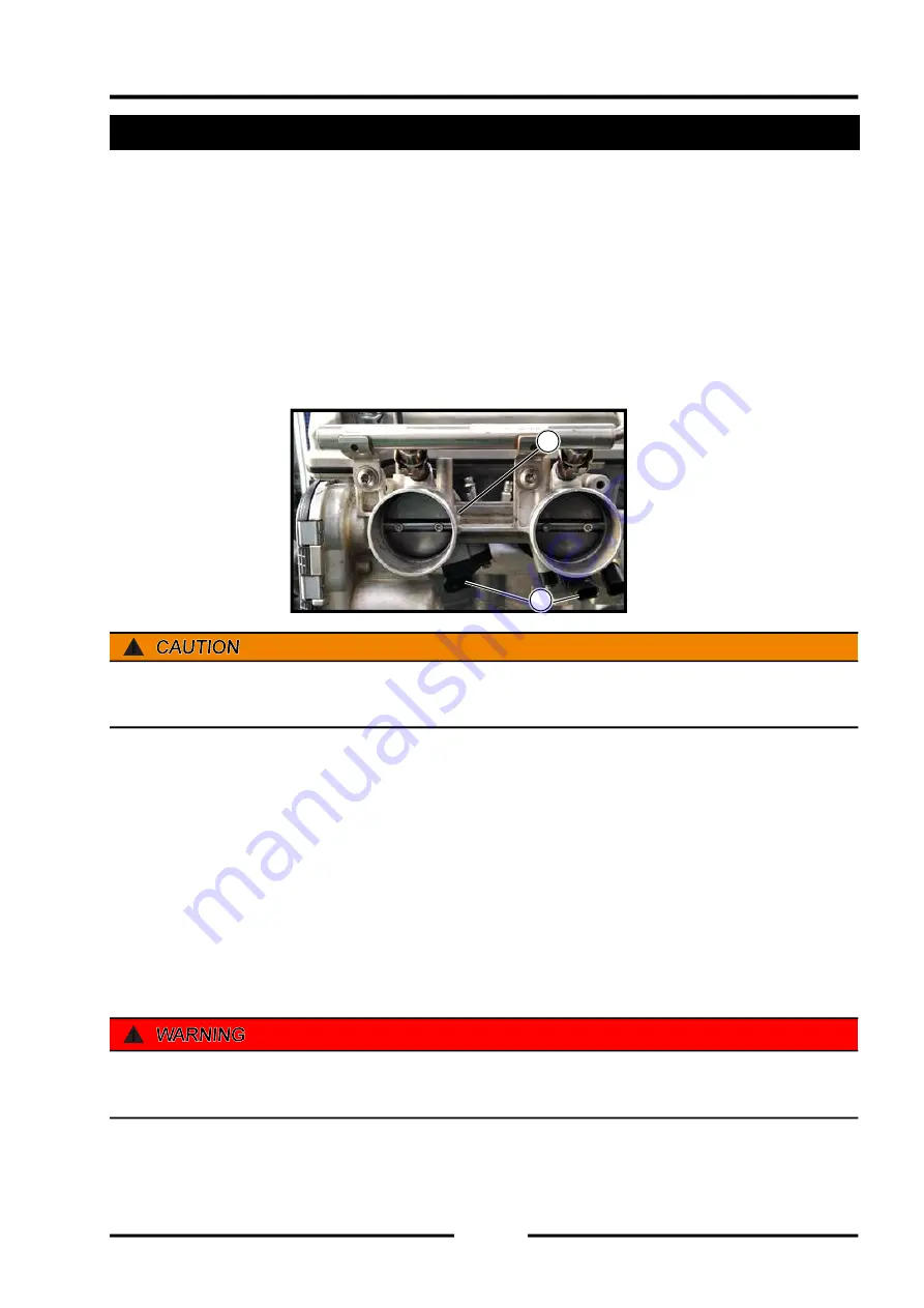
Open the cargo box to see the electronic throttle valve body assembly (see A in the fi gure below).
A
B
!
After the electronic throttle body is installed, you must make sure to perform a throttle body self-
learning. After the self-learning is completed, start the vehicle and observe whether it works normally.
Disassembly requirements
◆
It is strictly forbidden to disassemble the charged electronic throttle body.
◆
The electronic throttle body can be disassembled after the vehicle is cooled to room temperature to
prevent the black cover and connectors from being wetted by the overheated antifreeze liquid.
◆
During the disassembly process, disassemble the mounting bolts diagonally, with even force, not
to damage the upper and lower mounting surfaces, and at the same time ensure that the electronic
throttle body does not fall or hit.
◆
The force of the return spring inside the electronic throttle body is relatively large. Be careful to hurt
your hands when pushing the valve plate gently.
!
It is forbidden to collide with the electronic throttle body during maintenance, and it is forbidden to use
the electronic throttle body after it has fallen.
Summary of Contents for S301000-20100A
Page 1: ...SERVICE MANUAL SSV 4 3 4 130 6 54...
Page 50: ...ENGINE LUBRICATION SYSTEM 3 1 2 Exploded view...
Page 63: ...EFI SYSTEM 3 2 2 Exploded view Exploded view...
Page 67: ...STARTING SYSTEM 3 3 2 Exploded view...
Page 75: ...CRANKCASE CRANKSHAFT BALANCE SHAFT 3 4 2 Explosive view...
Page 76: ...CRANKCASE CRANKSHAFT BALANCE SHAFT 3 4 3 Explosive view of Up and down the case sub assembly...
Page 100: ...CYLINDER HEAD CYLINDER PISTON CYLINDER HEAD CYLINDER PISTON 3 5 3 Exploded view...
Page 141: ...CVT SYSTEM 3 6 2 Exploded view...
Page 151: ...WATER PUMP ASSEMBLY 3 7 2 Exploded view...
Page 197: ...6 6 COOLING SYSTEM SPECIAL TOOLS AND SEALANTS Silicone Sealant Special tools and sealants...
Page 227: ...9 2 FRONT REAR SUSPENSION EXPLODED VIEW OF FRONT SUSPENSION...
Page 229: ...9 4 FRONT REAR SUSPENSION EXPLODED VIEW OF REAR SUSPENSION...
Page 247: ...10 5 WHEELS AND TIRES SPECIAL TOOLS Jack...
Page 261: ...11 4 BRAKE SYSTEM SPECIAL TOOLS Inside Circlip Pliers...
Page 314: ...14 4 ELECTRICAL SYSTEM EXPLODED VIEW...
Page 407: ...14 97 ELECTRICAL SYSTEM ELECTRIC SCHEMATIC DIAGRAM...


