2 -
23
MAINTENANCE
COOLING SYSTEM
Cooling System Overview
The engine coolant level is controlled, or maintained, by
the recovery system. The recovery system components
are the recovery bottle, radiator filler neck, radiator
pressure cap and connecting hose.
As coolant operating temperature increases, the
expanding (heated) excess coolant is forced out of the
radiator past the pressure cap and into the recovery
bottle. As engine coolant temperature decreases the
contracting (cooled) coolant is drawn back up from the
tank past the pressure cap and into the radiator.
!
Some coolant level drop on new machines is normal
as the system is purging itself of trapped air. Observe
coolant levels often during break-in period.
Overheating of engine could occur if air is not fully
purged from system.
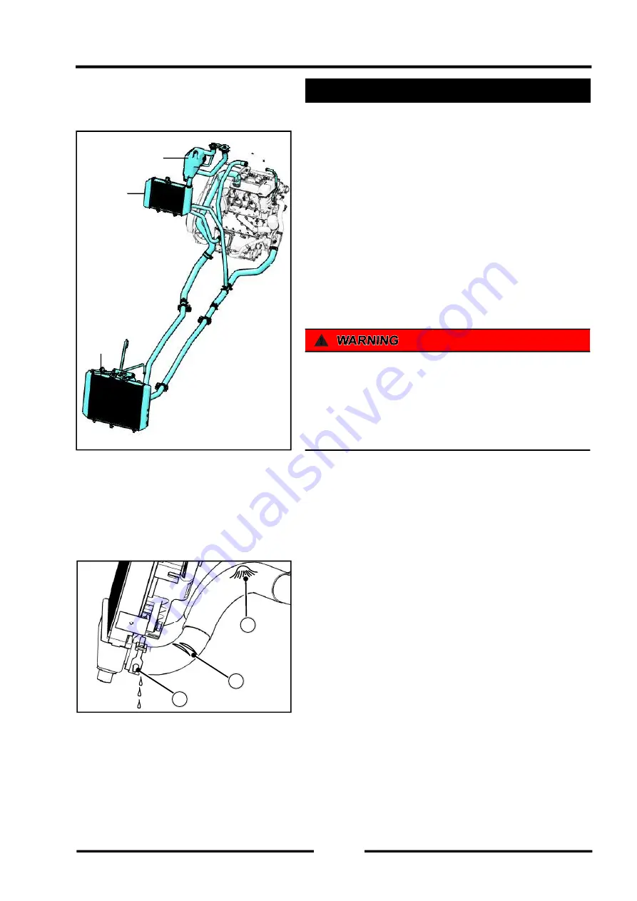
Cooling System Hoses
The high pressure inside the radiator hose can cause
coolant to leak
【
A
】
or the hose to burst if the line is not
properly maintained. Visually inspect the hoses for signs
of deterioration. Squeeze the hoses. A hose should not
be hard and brittle, nor should it be soft or swollen.
Replace the hose if any fraying, cracks
【
B
】
or bulges
【
C
】
are noticed.
Check that the hoses are securely connected and
clamps are tightened correctly.
◆
Inspect all vehicle hoses for cracks, deterioration,
abrasion or leaks. Replace if necessary.
◆
Check tightness and condition of all hose spring
clamps. Replace if necessary.
◆
Inspect all engine hoses for cracks, deterioration,
abrasion or leaks. Replace if necessary.
◆
Check tightness and condition of all hose spring
clamps. Replace if necessary.
Engine oil
raditor
Sub water tank
Engine
raditor
A
B
C
Summary of Contents for S301000-20100A
Page 1: ...SERVICE MANUAL SSV 4 3 4 130 6 54...
Page 50: ...ENGINE LUBRICATION SYSTEM 3 1 2 Exploded view...
Page 63: ...EFI SYSTEM 3 2 2 Exploded view Exploded view...
Page 67: ...STARTING SYSTEM 3 3 2 Exploded view...
Page 75: ...CRANKCASE CRANKSHAFT BALANCE SHAFT 3 4 2 Explosive view...
Page 76: ...CRANKCASE CRANKSHAFT BALANCE SHAFT 3 4 3 Explosive view of Up and down the case sub assembly...
Page 100: ...CYLINDER HEAD CYLINDER PISTON CYLINDER HEAD CYLINDER PISTON 3 5 3 Exploded view...
Page 141: ...CVT SYSTEM 3 6 2 Exploded view...
Page 151: ...WATER PUMP ASSEMBLY 3 7 2 Exploded view...
Page 197: ...6 6 COOLING SYSTEM SPECIAL TOOLS AND SEALANTS Silicone Sealant Special tools and sealants...
Page 227: ...9 2 FRONT REAR SUSPENSION EXPLODED VIEW OF FRONT SUSPENSION...
Page 229: ...9 4 FRONT REAR SUSPENSION EXPLODED VIEW OF REAR SUSPENSION...
Page 247: ...10 5 WHEELS AND TIRES SPECIAL TOOLS Jack...
Page 261: ...11 4 BRAKE SYSTEM SPECIAL TOOLS Inside Circlip Pliers...
Page 314: ...14 4 ELECTRICAL SYSTEM EXPLODED VIEW...
Page 407: ...14 97 ELECTRICAL SYSTEM ELECTRIC SCHEMATIC DIAGRAM...


