14 -
75
ELECTRICAL SYSTEM
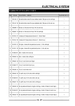
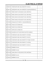
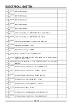
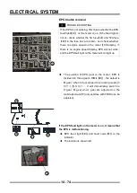
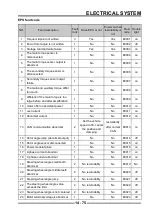
EPS fault code
NO.
Fault description
Fault
rank
Have EPS or not
Power on then
restorability or
not
Fault
code
Trouble
light
1
Torque midpoint not written
3
Yes
Yes
E0001
on
2
End of rotor angle is not written
1
No
No
E0002
off
3
Storage read and write failure
1
Yes
Yes
E0003
on
4
The main torque sensor is
disconnected
1
No
No
E0004
on
5
The main torque sensor output is
abnormal
1
No
No
E0005
on
6
The secondary torque sensor is
disconnected
1
No
No
E0006
on
7
Secondary torque sensor output
failure
1
No
No
E0007
on
8
The main and auxiliary torque diff er
too much
1
No
No
E0008
on
9
diff erenc of the main torque is too
large before and after amplifi cation
1
No
No
E0009
on
10
motor off er no assistant power
1
No
No
E0010
on
11
overcurrent
1
No
No
E0011
on
12
Abnormal current
1
No
No
E0012
on
13
CAN communication abnormal
2
Set the vehicle
speed to 30, cancel
the positive and
damping
restorability
after normal
CAN
E0013
on
14
Rotor angle jump (abnormal output)
1
No
No
E0014
off
15
Rotor angle sensor disconnected
1
No
No
E0015
on
16
Power module failure
1
No
No
E0016
on
17
A phase current abnormal
1
No
No
E0017
on
18
C phase current abnormal
1
No
No
E0018
on
19
Steering wheel angle small teeth
abnormal
2
No returnability
No
E0019
No
20
Steering wheel angle middle teeth
abnormal
2
No returnability
No
E0020
off
21
Steering wheel angle jump
2
No returnability
No
E0021
off
22
The steering wheel angle value
exceeds the limit
2
No returnability
No
E0022
off
23
Steering wheel angle is not centered
2
No returnability
No
E0023
off
24
Motor terminal voltage is abnormal
1
No
No
E0024
off
Summary of Contents for S301000-20100A
Page 1: ...SERVICE MANUAL SSV 4 3 4 130 6 54...
Page 50: ...ENGINE LUBRICATION SYSTEM 3 1 2 Exploded view...
Page 63: ...EFI SYSTEM 3 2 2 Exploded view Exploded view...
Page 67: ...STARTING SYSTEM 3 3 2 Exploded view...
Page 75: ...CRANKCASE CRANKSHAFT BALANCE SHAFT 3 4 2 Explosive view...
Page 76: ...CRANKCASE CRANKSHAFT BALANCE SHAFT 3 4 3 Explosive view of Up and down the case sub assembly...
Page 100: ...CYLINDER HEAD CYLINDER PISTON CYLINDER HEAD CYLINDER PISTON 3 5 3 Exploded view...
Page 141: ...CVT SYSTEM 3 6 2 Exploded view...
Page 151: ...WATER PUMP ASSEMBLY 3 7 2 Exploded view...
Page 197: ...6 6 COOLING SYSTEM SPECIAL TOOLS AND SEALANTS Silicone Sealant Special tools and sealants...
Page 227: ...9 2 FRONT REAR SUSPENSION EXPLODED VIEW OF FRONT SUSPENSION...
Page 229: ...9 4 FRONT REAR SUSPENSION EXPLODED VIEW OF REAR SUSPENSION...
Page 247: ...10 5 WHEELS AND TIRES SPECIAL TOOLS Jack...
Page 261: ...11 4 BRAKE SYSTEM SPECIAL TOOLS Inside Circlip Pliers...
Page 314: ...14 4 ELECTRICAL SYSTEM EXPLODED VIEW...
Page 407: ...14 97 ELECTRICAL SYSTEM ELECTRIC SCHEMATIC DIAGRAM...


