STARTING SYSTEM
3-3-8
A
A
A
A
B
B
B
B
C
C
Disassemble the starting overrunning clutch
◆
Take out the starting driven gear assembly
【
A
】
from the overrunning clutch
◆
Check whether the bearing surface of the starting
driven gear and the bushing surface are worn,
check whether the bearing surface of the starting
driven gear and the bushing surface are worn and
damaged
◆
Remove 8 connecting bolts
【
B
】
to separate the
overrunning clutch from the magneto rotor
◆
Separate the one-way assembly from the fi xing seat,
and check whether the roller surface in the one-way
assembly is worn or damaged
Install the starting overrunning clutch
◆
Assemble the starting overrunning clutch
【
B
】
◆
Apply thread fastening glue to the threaded surface
of the mounting bolt
【
A
】
, assemble the starting
overrunning clutch and the magneto rotor, and
tighten the bolts
Bolt
【
A
】
9.8 N·m (1 kgf·m, 87 in•lb)
Summary of Contents for S301000-20100A
Page 1: ...SERVICE MANUAL SSV 4 3 4 130 6 54...
Page 50: ...ENGINE LUBRICATION SYSTEM 3 1 2 Exploded view...
Page 63: ...EFI SYSTEM 3 2 2 Exploded view Exploded view...
Page 67: ...STARTING SYSTEM 3 3 2 Exploded view...
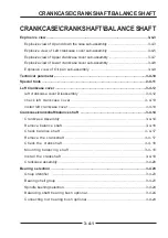
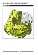
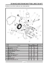
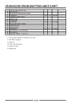
Page 75: ...CRANKCASE CRANKSHAFT BALANCE SHAFT 3 4 2 Explosive view...
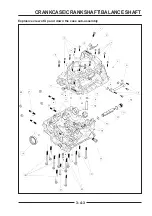
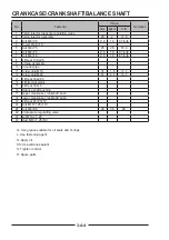
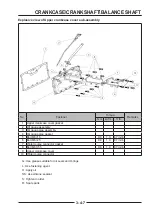
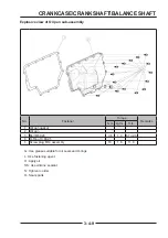
Page 76: ...CRANKCASE CRANKSHAFT BALANCE SHAFT 3 4 3 Explosive view of Up and down the case sub assembly...
Page 100: ...CYLINDER HEAD CYLINDER PISTON CYLINDER HEAD CYLINDER PISTON 3 5 3 Exploded view...
Page 141: ...CVT SYSTEM 3 6 2 Exploded view...
Page 151: ...WATER PUMP ASSEMBLY 3 7 2 Exploded view...
Page 197: ...6 6 COOLING SYSTEM SPECIAL TOOLS AND SEALANTS Silicone Sealant Special tools and sealants...
Page 227: ...9 2 FRONT REAR SUSPENSION EXPLODED VIEW OF FRONT SUSPENSION...
Page 229: ...9 4 FRONT REAR SUSPENSION EXPLODED VIEW OF REAR SUSPENSION...
Page 247: ...10 5 WHEELS AND TIRES SPECIAL TOOLS Jack...
Page 261: ...11 4 BRAKE SYSTEM SPECIAL TOOLS Inside Circlip Pliers...
Page 314: ...14 4 ELECTRICAL SYSTEM EXPLODED VIEW...
Page 407: ...14 97 ELECTRICAL SYSTEM ELECTRIC SCHEMATIC DIAGRAM...


