CRANKCASE\CRANKSHAFT\BALANCE SHAFT
3-4-1
CRANKCASE\CRANKSHAFT\BALANCE SHAFT
Explosive view...............................................................................................3-4-3
Explosive view of Up and down the case sub-assembly ...........................................3-4-3
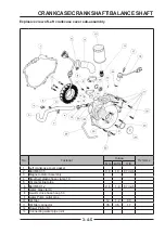
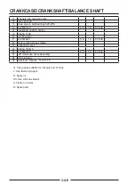
Explosive view of Left crankcase cover sub-assembly ..........................................3-4-5
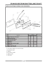
Explosive view of Upper crankcase cover sub-assembly ..........................................3-4-7
Explosive view of Lower crankcase cover sub-assembly ..........................................3-4-8
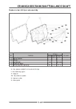
Explosive view of Oil pan sub-assembly ........................................................3-4-9
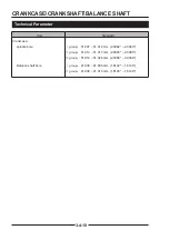
Technical parameter..............................................................................................3-4-10
Technical parameter..............................................................................................3-4-10
Special tools ...............................................................................................................
Special tools ...............................................................................................................3-4-11
11
Left Crankcase cover .................................................................................................
Left Crankcase cover .................................................................................................3-4-122
left crankcase cover Disassembly ..................................................................3-4-12
check left crankcase cover ..................................................................3-4-13
install left crankcase cover .............................................................................3-4-13
Crankcase\crankshaft\balance shaft ......................................................................
Crankcase\crankshaft\balance shaft ......................................................................3-4-14
14
Crankcase Assembly ...........................................................................3-4-14
Remove balance shaft ...........................................................................3-4-16
Check balance shaft ...........................................................................3-4-17
Remove the crankshaft ......................................................................3-4-17
Check the crankshaft .......................................................................3-4-18
Mounting balancing shaft ..................................................................3-4-19
Install the crankshaft ...........................................................................3-4-19
Crankcase assembly ........................................................................................3-4-20
Bearing selection ............................................................................................
Bearing selection ............................................................................................3-4-23
23
Group identifi er ...................................................................................................3-4-23
Bearing shell group ........................................................................................3-4-23
Spindle bushing selection .......................................................................................3-4-24
Balancing shaft bearing bush optional .......................................................3-4-24
Connecting rod bearing bush optional .......................................................3-4-24
Summary of Contents for S301000-20100A
Page 1: ...SERVICE MANUAL SSV 4 3 4 130 6 54...
Page 50: ...ENGINE LUBRICATION SYSTEM 3 1 2 Exploded view...
Page 63: ...EFI SYSTEM 3 2 2 Exploded view Exploded view...
Page 67: ...STARTING SYSTEM 3 3 2 Exploded view...
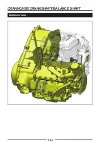
Page 75: ...CRANKCASE CRANKSHAFT BALANCE SHAFT 3 4 2 Explosive view...
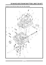
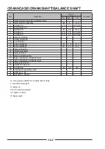
Page 76: ...CRANKCASE CRANKSHAFT BALANCE SHAFT 3 4 3 Explosive view of Up and down the case sub assembly...
Page 100: ...CYLINDER HEAD CYLINDER PISTON CYLINDER HEAD CYLINDER PISTON 3 5 3 Exploded view...
Page 141: ...CVT SYSTEM 3 6 2 Exploded view...
Page 151: ...WATER PUMP ASSEMBLY 3 7 2 Exploded view...
Page 197: ...6 6 COOLING SYSTEM SPECIAL TOOLS AND SEALANTS Silicone Sealant Special tools and sealants...
Page 227: ...9 2 FRONT REAR SUSPENSION EXPLODED VIEW OF FRONT SUSPENSION...
Page 229: ...9 4 FRONT REAR SUSPENSION EXPLODED VIEW OF REAR SUSPENSION...
Page 247: ...10 5 WHEELS AND TIRES SPECIAL TOOLS Jack...
Page 261: ...11 4 BRAKE SYSTEM SPECIAL TOOLS Inside Circlip Pliers...
Page 314: ...14 4 ELECTRICAL SYSTEM EXPLODED VIEW...
Page 407: ...14 97 ELECTRICAL SYSTEM ELECTRIC SCHEMATIC DIAGRAM...


