CRANKCASE\CRANKSHAFT\BALANCE SHAFT
3-4-22
22
33
44
55
66
77
88
99
10
10
11
11
12
12
13
13
11
22
33
44
55
66
77
88
99
10
10
11
11
12
12
13
13
14
14
15
15
11
◆
◆
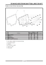
Tighten the bolts in sequence to the specifi ed torque.
Tighten the bolts in sequence to the specifi ed torque.
Bolt M8
25 N·m (2.5 kgf·m, 18.4 ft·lb
ft·lb)
Bolt M6
9.8 N·m (1 kgf·m, 89 in·lbs
in·lbs)
◆
Take a new rotary shaft oil seal
【
A
】
and apply a
proper amount of oil to the lip and outer ring surface.
With one side of the sealing lip facing inwards, press
vertically into the crankcase using the crankshaft oil
seal pressing tool
【
B
】
.
◆
Install the oil pump assembly (see lubrication
System section).
◆
Take a new oil pan gasket
【
C
】
, put it into the oil
pan, tighten the bolts in sequence
【
D
】
.
Bolt
【
D
】
9.8 N·m (1 kgf·m, 89 in·lbs
in·lbs)
A
A
C
C
D
D
B
B
Summary of Contents for S301000-20100A
Page 1: ...SERVICE MANUAL SSV 4 3 4 130 6 54...
Page 50: ...ENGINE LUBRICATION SYSTEM 3 1 2 Exploded view...
Page 63: ...EFI SYSTEM 3 2 2 Exploded view Exploded view...
Page 67: ...STARTING SYSTEM 3 3 2 Exploded view...
Page 75: ...CRANKCASE CRANKSHAFT BALANCE SHAFT 3 4 2 Explosive view...
Page 76: ...CRANKCASE CRANKSHAFT BALANCE SHAFT 3 4 3 Explosive view of Up and down the case sub assembly...
Page 100: ...CYLINDER HEAD CYLINDER PISTON CYLINDER HEAD CYLINDER PISTON 3 5 3 Exploded view...
Page 141: ...CVT SYSTEM 3 6 2 Exploded view...
Page 151: ...WATER PUMP ASSEMBLY 3 7 2 Exploded view...
Page 197: ...6 6 COOLING SYSTEM SPECIAL TOOLS AND SEALANTS Silicone Sealant Special tools and sealants...
Page 227: ...9 2 FRONT REAR SUSPENSION EXPLODED VIEW OF FRONT SUSPENSION...
Page 229: ...9 4 FRONT REAR SUSPENSION EXPLODED VIEW OF REAR SUSPENSION...
Page 247: ...10 5 WHEELS AND TIRES SPECIAL TOOLS Jack...
Page 261: ...11 4 BRAKE SYSTEM SPECIAL TOOLS Inside Circlip Pliers...
Page 314: ...14 4 ELECTRICAL SYSTEM EXPLODED VIEW...
Page 407: ...14 97 ELECTRICAL SYSTEM ELECTRIC SCHEMATIC DIAGRAM...


