ENGINE TOP END
ENGINE TOP END
3-5-24
Combustion Area
NOTE
NOTE
The valves can be re-faced or end ground, if necessary.
They must be replaced if extensively worn, burnt, bent
or damaged.
◆
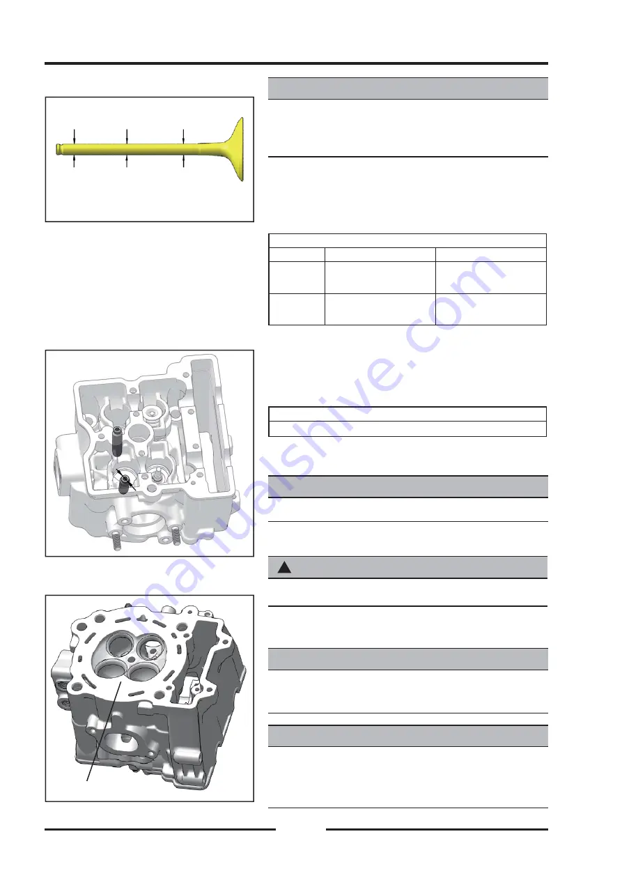
Measure diameter of valve stem with a micrometer
in three places, then rotate 90° and measure
again (take six measurements total). Compare to
specifi cations.
Valve Stem Diameter:
Standard
Service Limit
Exhaust:
5.455 ~ 5.470 mm
(0.2147" ~ 0.2153")
————
Inlet:
5.475 ~ 5.490 mm
(0.2155" ~ 0.2161")
————
◆
Measure diameter of valve stem with a micrometer
in three places, then rotate 90° and measure
again (take six measurements total). Compare to
specifi cations.
Valve Guide I.D.:
5.500 - 5.515 mm(0.2165" ~ 0.2171")
◆
Be sure to measure each guide and valve
combination individually.
NOTE
NOTE
The valve guides cannot be replaced.
Combustion Chamber Cleaning
Combustion Chamber Cleaning
!
WARNING
WARNING
Wear eye protection during combustion chamber cleaning.
◆
Clean all accumulated carbon deposits from
combustion chambers and valve seat area.
NOTE
NOTE
Carbon Clean Fuel Treatment can be used to help
remove carbon deposits.
CAUTION
CAUTION
Do not use a metal scraper, a coarse wire brush or
abrasive cleaners to clean the cylinder head. Damage
may result.
Summary of Contents for SNARLER ATV 2021 Series
Page 1: ...SERVICE MANUAL ATV SERIES PRODUCTS 20210804 V01...
Page 39: ...ENGINE LUBRICATION SYSTEM ENGINE LUBRICATION SYSTEM 3 1 2 Exploded view...
Page 99: ...ENGINE COOLING SYSTEM ENGINE COOLING SYSTEM 3 4 2 Exploded view...
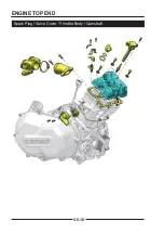
Page 120: ...ENGINE TOP END ENGINE TOP END 3 5 10 Spark Plug Valve Cover Throttle Body Camshaft...
Page 153: ...CVT SYSTEM CVT SYSTEM 3 6 2 L L G G G G R R Lh Lh R R R R Exploded view...
Page 155: ...CVT SYSTEM CVT SYSTEM 3 6 4 R R R R G G R R L L Lh Lh M M G G G G G G...
Page 185: ...4 13 FRONT AND REAR DIFFERENTIAL FRONT AND REAR DIFFERENTIAL...
Page 212: ...COOLING SYSTEM 6 6 Special tools and sealants Silicone Sealant...
Page 230: ...FRONT REAR SUSPENSION 9 2 Exploded view of Front suspension...
Page 232: ...FRONT REAR SUSPENSION 9 4 Exploded view of Rear suspension...
Page 249: ...WHEELS AND TIRES 10 5 Special Tools Jack...
Page 264: ...BRAKE SYSTEM 11 5 Inside Circlip Pliers Special tool...
Page 276: ...STEERING SYSTEM 12 2 Exploded View of Steering System 1 2 A A 3 4 5 5 5 6 3 B...
Page 323: ...ELECTRICAL SYSTEM 14 15 EFI system Schematic diagram of EFI system...
Page 383: ...ELECTRICAL SYSTEM 14 75 B10 B11 B12 B14 B15 B16...

