CVT SYSTEM
CVT SYSTEM
3-6-10
Drive Belt Removal
Removal
◆
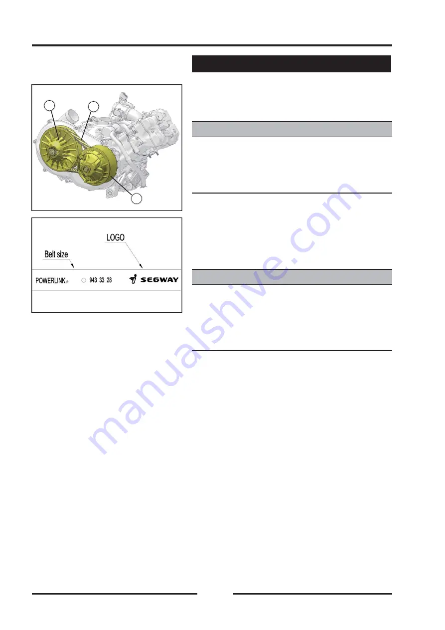
Remove the drive pulley
【
A
】
(see Drive Pulley
Removal).
NOTE
NOTE
Before removing the drive belt, observe the direction
of the informations
【
A
】
(Such as manufacturers name
and arrow marks) printed on the belt so that it may be
reinstalled on the pulleys as originally.
◆
Lift the drive belt
【
B
】
off the driven pulley
【
C
】
.
Drive Belt Installation
Drive Belt Installation
NOTE
NOTE
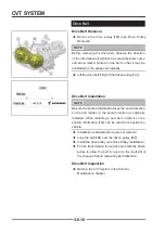
Be sure the printed information faces the same direction
so the belt rotates in the same direction as originally
installed. When installing a new belt, install it so the
printed information
【
A
】
can be read from beside the
vehicle.
◆
Installation is basically the reverse of removal.
◆
Loop the belt
【
B
】
over the driven pulley
【
C
】
.
◆
Install the drive pulley (see Drive Pulley Installation).
◆
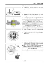
Put the transmission in neutral, and rotate the driven
pulley to allow the belt to return to the top
【
A
】
of
the sheaves, before measuring belt defl ection.
Drive Belt Inspection
Drive Belt Inspection
◆
Refer to the CVT System in the Periodic
Maintenance chapter.
B
B
C
C
A
A
Drive Belt
Summary of Contents for SNARLER ATV 2021 Series
Page 1: ...SERVICE MANUAL ATV SERIES PRODUCTS 20210804 V01...
Page 39: ...ENGINE LUBRICATION SYSTEM ENGINE LUBRICATION SYSTEM 3 1 2 Exploded view...
Page 99: ...ENGINE COOLING SYSTEM ENGINE COOLING SYSTEM 3 4 2 Exploded view...
Page 120: ...ENGINE TOP END ENGINE TOP END 3 5 10 Spark Plug Valve Cover Throttle Body Camshaft...
Page 153: ...CVT SYSTEM CVT SYSTEM 3 6 2 L L G G G G R R Lh Lh R R R R Exploded view...
Page 155: ...CVT SYSTEM CVT SYSTEM 3 6 4 R R R R G G R R L L Lh Lh M M G G G G G G...
Page 185: ...4 13 FRONT AND REAR DIFFERENTIAL FRONT AND REAR DIFFERENTIAL...
Page 212: ...COOLING SYSTEM 6 6 Special tools and sealants Silicone Sealant...
Page 230: ...FRONT REAR SUSPENSION 9 2 Exploded view of Front suspension...
Page 232: ...FRONT REAR SUSPENSION 9 4 Exploded view of Rear suspension...
Page 249: ...WHEELS AND TIRES 10 5 Special Tools Jack...
Page 264: ...BRAKE SYSTEM 11 5 Inside Circlip Pliers Special tool...
Page 276: ...STEERING SYSTEM 12 2 Exploded View of Steering System 1 2 A A 3 4 5 5 5 6 3 B...
Page 323: ...ELECTRICAL SYSTEM 14 15 EFI system Schematic diagram of EFI system...
Page 383: ...ELECTRICAL SYSTEM 14 75 B10 B11 B12 B14 B15 B16...


