CVT SYSTEM
CVT SYSTEM
3-6-21
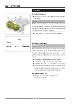
Drive Pulley and Driven Pulley Installation
Drive Pulley and Driven Pulley Installation
◆
Clean the following portions with an oil-less
cleaning fluid such as trichloroethylene or
acetone.
Fixed Sheave Tapered Portion
【
A
】
Crankshaft Tapered Portion
【
B
】
!
WARNING
WARNING
These cleaning fl uids are usually highly fl ammable and
harmful if breathed for prolonged periods. Be sure to
heed the fl uid manufacturer’s warnings.
◆
Combine the CVT Drive Pulley Assembly
【
C
】
,
CVT Driven Pulley Assembly
【
D
】
and Belt
【
E
】
and install them to taper
【
B
】
of the Crankshaft and
spline of the Transmission Main Shaft.
◆
Install
Spacer 12×28×6
【
G
】
CVT Drive Pulley Bolt M12×1.25×142
【
F
】
Spacer 10.5×36×8
【
J
】
CVT Driven Pulley Bolt M10×1.25×80
【
H
】
◆
Tighten the CVT Pulley Bolt to the specifi ed torque.
Torque
Drive Pulley Bolt
120 N•m (12.2 kgf•m, 88 ft•lb)
Drive Pulley Bolt
80 N•m (8.2 kgf•m, 59 ft•lb)
Special Tool -
Drive Pulley Holder
【
K
】
: E01GZ0000012
Belt Separate Bolt
【
L
】
:
E01GZ0000013
◆
Remove the Drive Pulley Holder
【
K
】
,
Belt
Separate Bolt
【
L
】
and
Bolt M8
【
M
】
.
◆
Install the CVT Outer Cover (See CVT Cover
Installation)
A
A
B
B
C
C
D
D
E
E
JJ
H
H
G
G
F
F
LL
M
M
K
K
K
K
F
F
Summary of Contents for SNARLER ATV 2021 Series
Page 1: ...SERVICE MANUAL ATV SERIES PRODUCTS 20210804 V01...
Page 39: ...ENGINE LUBRICATION SYSTEM ENGINE LUBRICATION SYSTEM 3 1 2 Exploded view...
Page 99: ...ENGINE COOLING SYSTEM ENGINE COOLING SYSTEM 3 4 2 Exploded view...
Page 120: ...ENGINE TOP END ENGINE TOP END 3 5 10 Spark Plug Valve Cover Throttle Body Camshaft...
Page 153: ...CVT SYSTEM CVT SYSTEM 3 6 2 L L G G G G R R Lh Lh R R R R Exploded view...
Page 155: ...CVT SYSTEM CVT SYSTEM 3 6 4 R R R R G G R R L L Lh Lh M M G G G G G G...
Page 185: ...4 13 FRONT AND REAR DIFFERENTIAL FRONT AND REAR DIFFERENTIAL...
Page 212: ...COOLING SYSTEM 6 6 Special tools and sealants Silicone Sealant...
Page 230: ...FRONT REAR SUSPENSION 9 2 Exploded view of Front suspension...
Page 232: ...FRONT REAR SUSPENSION 9 4 Exploded view of Rear suspension...
Page 249: ...WHEELS AND TIRES 10 5 Special Tools Jack...
Page 264: ...BRAKE SYSTEM 11 5 Inside Circlip Pliers Special tool...
Page 276: ...STEERING SYSTEM 12 2 Exploded View of Steering System 1 2 A A 3 4 5 5 5 6 3 B...
Page 323: ...ELECTRICAL SYSTEM 14 15 EFI system Schematic diagram of EFI system...
Page 383: ...ELECTRICAL SYSTEM 14 75 B10 B11 B12 B14 B15 B16...


