FUEL SYSTEM
5 -
4
B
C
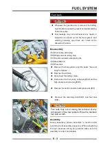
Fuel Pump
!
Fuel leakage may occur whenever any repair or
inspection is carried out on the fuel system, and
welding, smoking, open fi res, etc., shall not be allowed
in the area.
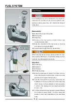
Disassembly
【
A
】
Install screw cap on fuel pump
【
B
】
Fuel pump
【
C
】
Seal ring
◆
R e m o v e t h e f u e l p u m p i n s t a l l s c r e w c a p
counterclockwise
【
A
】;
◆
Mark the orientation of the fuel pump on the tank
and remove the fuel pump
【
B
】;
◆
Keep the seal ring
【
C
】
well to prevent loss
;
!
After removing the fuel pump, please protect the fuel
tank opening effectively to avoid debris falling into the
fuel tank, thus damaging the fuel pump.
Inspection
【
A
】
cable plug
【
B
】
Position 1
【
C
】
Position 2
【
D
】
Pressure gauge
◆
Move the float lever to check if it is free to move.
Float components should be free to return to lower
positions.If not, replace the fuel pump.
◆
Test the fuel position sensor by connecting the
multimeter to the two middle pins of the cable plug
【
A
】
. Shown on the multimeter in full fuel position
1 to 160 + 5 Ω, displayed on the empty fuel position
2 to 40 + 5 Ω.
◆
The fuel pump outlet pressure was measured through
the pressure gauge
【
D
】
, and the measured
pressure value was 330±20Kpa in the electrified
state.
A
B
C
A
D
Summary of Contents for SNARLER ATV 2021 Series
Page 1: ...SERVICE MANUAL ATV SERIES PRODUCTS 20210804 V01...
Page 39: ...ENGINE LUBRICATION SYSTEM ENGINE LUBRICATION SYSTEM 3 1 2 Exploded view...
Page 99: ...ENGINE COOLING SYSTEM ENGINE COOLING SYSTEM 3 4 2 Exploded view...
Page 120: ...ENGINE TOP END ENGINE TOP END 3 5 10 Spark Plug Valve Cover Throttle Body Camshaft...
Page 153: ...CVT SYSTEM CVT SYSTEM 3 6 2 L L G G G G R R Lh Lh R R R R Exploded view...
Page 155: ...CVT SYSTEM CVT SYSTEM 3 6 4 R R R R G G R R L L Lh Lh M M G G G G G G...
Page 185: ...4 13 FRONT AND REAR DIFFERENTIAL FRONT AND REAR DIFFERENTIAL...
Page 212: ...COOLING SYSTEM 6 6 Special tools and sealants Silicone Sealant...
Page 230: ...FRONT REAR SUSPENSION 9 2 Exploded view of Front suspension...
Page 232: ...FRONT REAR SUSPENSION 9 4 Exploded view of Rear suspension...
Page 249: ...WHEELS AND TIRES 10 5 Special Tools Jack...
Page 264: ...BRAKE SYSTEM 11 5 Inside Circlip Pliers Special tool...
Page 276: ...STEERING SYSTEM 12 2 Exploded View of Steering System 1 2 A A 3 4 5 5 5 6 3 B...
Page 323: ...ELECTRICAL SYSTEM 14 15 EFI system Schematic diagram of EFI system...
Page 383: ...ELECTRICAL SYSTEM 14 75 B10 B11 B12 B14 B15 B16...


