COOLING SYSTEM
6 -
9
!
◆
The start and stop of the radiator fan are controlled
by the vehicle ECU. When the water temperature
of the engine cylinder head reaches 88°C, the fan
automatically starts; until the water temperature of
the cylinder head drops below 83°C, the radiator
fan automatically stops. Do not touch the radiator
fan when it is rotating, as this may cause injury.
◆
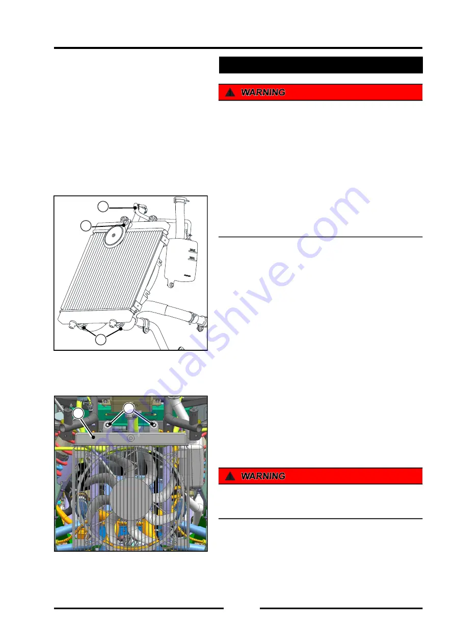
When disassembling the radiator, it must be done
in a low temperature vehicle and in a flameout
state.
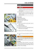
Disassembly
【
A
】
Horn mounting bolt
【
B
】
Radiator overfl ow pipe clamp
【
C
】
Hose clamp for front section of radiator
【
D
】
Radiator mounting bolt M6×25
【
E
】
Radiator
◆
Remove the front plastic part of the vehicle(See the
vehicle body section for details)
◆
Remove the speaker mounting bolt
【
A
】
, and
remove the speaker
◆
Use tools to remove the radiator overflow pipe
clamp, pull out the overfl ow pipe radiator front hose
clamp, and remove the left and right 2 radiator front
hose
◆
Remove the 2 radiator mounting bolts
◆
Remove the radiator
!
Do not touch the radiator core. This may damage the
heat sink, resulting in reduced cooling effi ciency
A
B
C
Radiator removal
D
E
Summary of Contents for SNARLER ATV 2021 Series
Page 1: ...SERVICE MANUAL ATV SERIES PRODUCTS 20210804 V01...
Page 39: ...ENGINE LUBRICATION SYSTEM ENGINE LUBRICATION SYSTEM 3 1 2 Exploded view...
Page 99: ...ENGINE COOLING SYSTEM ENGINE COOLING SYSTEM 3 4 2 Exploded view...
Page 120: ...ENGINE TOP END ENGINE TOP END 3 5 10 Spark Plug Valve Cover Throttle Body Camshaft...
Page 153: ...CVT SYSTEM CVT SYSTEM 3 6 2 L L G G G G R R Lh Lh R R R R Exploded view...
Page 155: ...CVT SYSTEM CVT SYSTEM 3 6 4 R R R R G G R R L L Lh Lh M M G G G G G G...
Page 185: ...4 13 FRONT AND REAR DIFFERENTIAL FRONT AND REAR DIFFERENTIAL...
Page 212: ...COOLING SYSTEM 6 6 Special tools and sealants Silicone Sealant...
Page 230: ...FRONT REAR SUSPENSION 9 2 Exploded view of Front suspension...
Page 232: ...FRONT REAR SUSPENSION 9 4 Exploded view of Rear suspension...
Page 249: ...WHEELS AND TIRES 10 5 Special Tools Jack...
Page 264: ...BRAKE SYSTEM 11 5 Inside Circlip Pliers Special tool...
Page 276: ...STEERING SYSTEM 12 2 Exploded View of Steering System 1 2 A A 3 4 5 5 5 6 3 B...
Page 323: ...ELECTRICAL SYSTEM 14 15 EFI system Schematic diagram of EFI system...
Page 383: ...ELECTRICAL SYSTEM 14 75 B10 B11 B12 B14 B15 B16...

