2 -
9
MAINTENANCE
MAINTENANCE
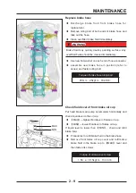
Replace brake hose
◆
Discharge brake fluid from brake hose for
replacement.
◆
Remove oiling bolt of both ends of brake hose and
take out the hose.
◆
Clean overfi lled brake fl uid immediately
!
!
WARNING
WARNING
Brake fluid may quickly destroy painting surface. Any
Brake fluid may quickly destroy painting surface. Any
overfi lled fl uids should be cleaned immediately
overfi lled fl uids should be cleaned immediately
◆
Use new fl at washer on each end of hose connector.
◆
assemble new brake hose in position (refer to
annex) and fasten oiling bolt.
Torque of brake hose oiling bolt
25N·m
25N·m
(
(
2.5kgf·m
2.5kgf·m
,
,
18.4ft·lb
18.4ft·lb
)
)
Check fl uid level of front brake oil cup
Put hand brake main pump accumulator horizontally and
check liquid level in the oil cup.
◆
【
MAX
】
—highest fl uid level of brake oil cup
◆
【
MIN
】
—lowest fl uid level of brake oil cup.
If liquid level is lower than
【
MIN
】,
check and refill
brake fl uid.
◆
Procedures to refi ll brake fl uid in the brake hose
◆
Remove front brake oil cup cover and refill same
brake fluid in the brake cup to
【
MAX
】
level and
then fasten its screws.
Torque of oil cap cover screw
1.5N·m
(
(
0.15kgf·m
0.15kgf·m
,
,
13.3in·lb
13.3in·lb
)
)
MAX
MAX
MIN
MIN
Summary of Contents for SNARLER ATV 2021 Series
Page 1: ...SERVICE MANUAL ATV SERIES PRODUCTS 20210804 V01...
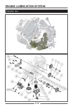
Page 39: ...ENGINE LUBRICATION SYSTEM ENGINE LUBRICATION SYSTEM 3 1 2 Exploded view...
Page 99: ...ENGINE COOLING SYSTEM ENGINE COOLING SYSTEM 3 4 2 Exploded view...
Page 120: ...ENGINE TOP END ENGINE TOP END 3 5 10 Spark Plug Valve Cover Throttle Body Camshaft...
Page 153: ...CVT SYSTEM CVT SYSTEM 3 6 2 L L G G G G R R Lh Lh R R R R Exploded view...
Page 155: ...CVT SYSTEM CVT SYSTEM 3 6 4 R R R R G G R R L L Lh Lh M M G G G G G G...
Page 185: ...4 13 FRONT AND REAR DIFFERENTIAL FRONT AND REAR DIFFERENTIAL...
Page 212: ...COOLING SYSTEM 6 6 Special tools and sealants Silicone Sealant...
Page 230: ...FRONT REAR SUSPENSION 9 2 Exploded view of Front suspension...
Page 232: ...FRONT REAR SUSPENSION 9 4 Exploded view of Rear suspension...
Page 249: ...WHEELS AND TIRES 10 5 Special Tools Jack...
Page 264: ...BRAKE SYSTEM 11 5 Inside Circlip Pliers Special tool...
Page 276: ...STEERING SYSTEM 12 2 Exploded View of Steering System 1 2 A A 3 4 5 5 5 6 3 B...
Page 323: ...ELECTRICAL SYSTEM 14 15 EFI system Schematic diagram of EFI system...
Page 383: ...ELECTRICAL SYSTEM 14 75 B10 B11 B12 B14 B15 B16...


